Section 12.1
Valve Lash Checking
Check and adjust the valve lash as follows:
Note: Adjust the valve lash when the engine is cold. Wait at least 30 minutes after shutdown, even if the engine ran only a short time.
Select a method for adjusting the valve lash. There are two acceptable methods for adjusting the valves, prior to checking the valve lash:
- In order, according to the timing sequence used for fuel injection (see Method One—Adjust Each Cylinder in Firing Order);
- By type of valve, depending on crankshaft position (see Method Two—Adjust All Valves Using Two Crankshaft Positions). See Figure
"Cylinder and Valve Layout"
for the cylinder and valve layout on both the 4– and 6–cylinder engines.

Figure 1. Cylinder and Valve Layout
Section 12.1.1
Method One — Adjust Each Cylinder in Firing Order
Method one allows you to adjust each cylinder in the order in which fuel is injected. The crankshaft must be repositioned after each cylinder is adjusted as listed in Table "Valve Adjustment (Method One)" .
|
Engine |
Crankshaft Position |
Cylinders |
|||||
|
4–Cylinder |
Ignition TDC |
1 |
3 |
4 |
2 |
N/A |
N/A |
|
Valve Overlap |
4 |
2 |
1 |
3 |
N/A |
N/A |
|
|
6–Cylinder |
Ignition TDC |
1 |
5 |
3 |
6 |
2 |
4 |
|
Valve Overlap |
6 |
2 |
4 |
1 |
5 |
3 |
|
Note: Clean the cylinder head cover before removing it.
- Remove the cylinder head cover. Refer to "1.1.1 Cylinder Head Cover Removal"
. See Figure
"Cylinder Head Cover"
.

1. Engine Trim Panel
5. Cylinder Head Cover
2. Charge-Air Manifold Gasket
6. Cylinder Head Gasket
3. Hexagon Socket-Head Bolt
7. Breather Hose
4. Sealing Washer
Figure 2. Cylinder Head Cover
- Remove the inspection cover on the flywheel housing.
- Install the engine barring tool J-46392
into the inspection hole on the flywheel housing. Refer to "1.13 Engine Barring Tool"
. See Figure
"Inspection Hole in the Flywheel Housing"
.
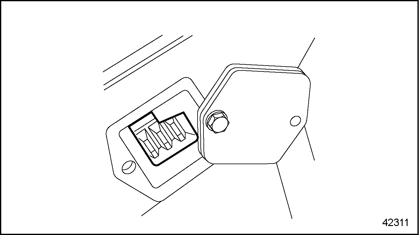
Figure 3. Inspection Hole in the Flywheel Housing
- For each cylinder, use the cranking tool to rotate the crankshaft until the piston is exactly at top dead center (TDC) in the compression stroke. The valves must be closed and it must be possible to turn the pushrods without effort.
Note: When the piston in cylinder #1 is at ignition TDC, the valves of cylinder #6 (cylinder #4 on the 4-cylinder engine) will overlap, meaning that both intake and exhaust valves are partially open, and show no measurable play when tested with a feeler gauge.
- Check each valve and if necessary, adjust it using the remaining steps.
- For each valve, measure the valve lash with a feeler gauge between the rocker arm and valve stem (exhaust valve) or valve bridge (intake valve). It should be possible to pull the feeler gauge through with no more than light resistance.
- If the value measured is within the range given in the "Check For" column listed in Table
"Valve Lash Checking and Adjustment"
, check the next valve.
Valve Type
Check for: mm (inches)
Adjust to: mm (inches)
Intake
0.30 to 0.60 (0.012 to 0.024)
0.40 (0.016)
Exhaust
0.50 to 0.80 (0.020 to 0.032)
0.60 (0.024)
Table 3. Valve Lash Checking and Adjustment
If the value measured is outside the range given in the "Check For" column listed in Table "Valve Lash Checking and Adjustment" , adjust the valve lash. Refer to "12.2 Adjusting Valve Lash" .
Section 12.1.2
Adjust All Valves Using Two Crankshaft Positions
Method two allows you to adjust all the valves using just two crankshaft positions.
Note: Clean the cylinder head cover before removing it.
- Remove the cylinder head cover. Refer to "1.1.1 Cylinder Head Cover Removal"
. See Figure
"Cylinder Head Cover"
.
1. Engine Trim Panel
5. Cylinder Head Cover
2. Charge-Air Manifold Gasket
6. Cylinder Head Gasket
3. Hexagon Socket-Head Bolt
7. Breather Hose
4. Sealing Washer
Figure 4. Cylinder Head Cover
- Remove the inspection cover on the flywheel housing.
Figure 5. Inspection Hole in the Flywheel Housing
- Install the engine barring tool J-46392 into the inspection hole on the flywheel housing. Refer to "1.13 Engine Barring Tool" . See Figure "Inspection Hole in the Flywheel Housing" .
- Using the cranking tool, rotate the crankshaft until cylinder #1 is at the ignition TDC position (all valves are closed) and cylinder #6 (cylinder #4 on a 4-cylinder engine) is at the valve overlap position (all valves are open).
- Check the valves in the "Ignition TDC" row listed in Table
"Valve Adjustment (Method Two)"
and adjust them (if necessary), using the remaining steps.
Engine
Cylinder #1 Crankshaft Position
Cylinders/Valve Types*
1
2
3
4
5
6
4–Cylinder
Ignition TDC
I/E
I
E
—
N/A
N/A
Valve Overlap
—
E
I
I/E
N/A
N/A
6–Cylinder
Ignition TDC
I/E
I
E
I
E
—
Valve Overlap
—
E
I
E
I
I/E
Table 5. Valve Adjustment (Method Two)
*NOTE: I = Intake Valve and E = Exhaust Valve - Using the cranking tool, rotate the crankshaft until cylinder #6 (cylinder #4 on a 4-cylinder engine) is at the ignition TDC position (all valves are closed) and cylinder #1 is at the valve overlap position (all valves are open).
- Using the same procedure, check the valves in the "Valve Overlap" row listed in Table "Valve Adjustment (Method Two)" and adjust them (if necessary), using the remaining steps.
- For each valve, measure the valve lash with a feeler gauge between the rocker arm and valve stem (exhaust valve) or valve bridge (intake valve). It should be possible to pull the feeler gauge through with no more than light resistance.
- If the value measured is within the range given in the "Check For" column listed in Table
"Valve Lash Checking and Adjustment"
, check the next valve.
Valve Type
Check For: mm (inches)
Adjust to: mm (inches)
Intake
0.30 to 0.60 (0.012 to 0.024)
0.40 (0.016)
Exhaust
0.50 to 0.80 (0.020 to 0.032)
0.60 (0.024)
Table 6. Valve Lash Checking and Adjustment
If the value measured is outside the range given in the "Check For" column listed in Table "Valve Lash Checking and Adjustment" , adjust the valve lash.
| MBE 900 Service Manual - 6SE414 |
| Generated on 10-13-2008 |
After carefully checking to be sure all pushrods are seated in the lifter and rocker arm, it is time for valve lash adjustment. 8. By installing the crankshaft dampener bolt back into the snout of the crankshaft, turn the engine