Section 5.5
PID 51, FMI 3, Flash Code 17, Throttle Plate Position Sensor Input Voltage High
The throttle plate position sensor input voltage is high due to a short or a faulty throttle.
Section 5.5.1
Troubleshooting PID 51, FMI 3, FLASH CODE 17
Troubleshoot as follows:
NOTICE: |
|
To avoid damage to the harness and connectors when disconnecting harness connectors, ensure the pulling force is applied to the connectors and not to the wires extending from the connectors. |
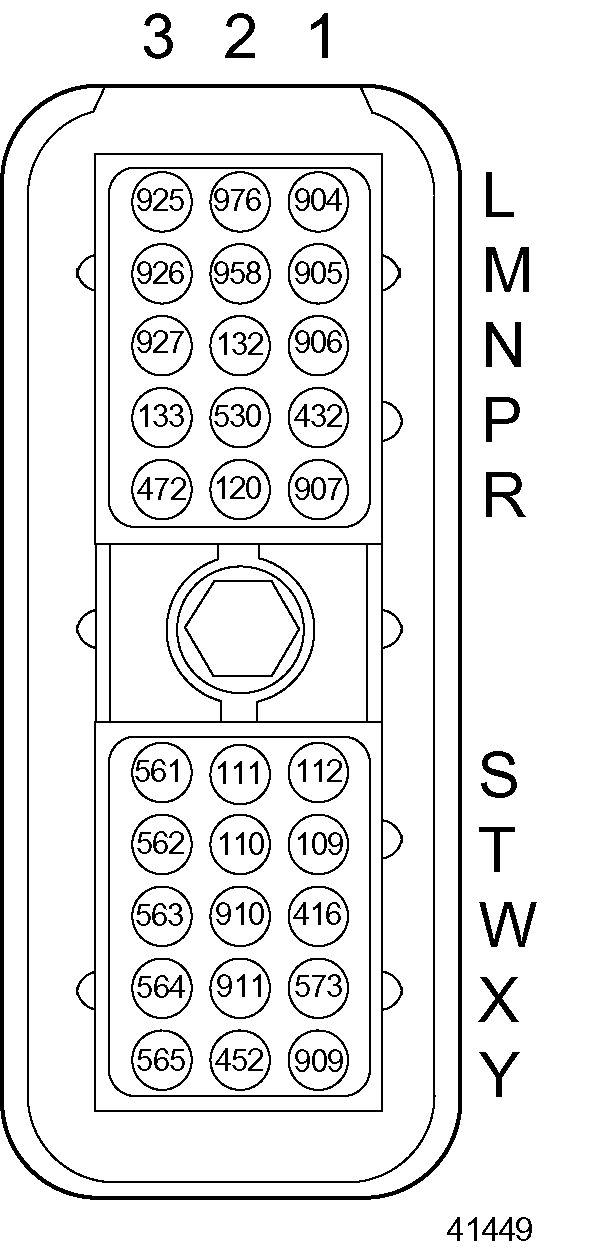
- Check wire 907 (dark green, throttle plate position) cavity R-1 in the Engine Sensor Harness (ESH) 30–pin connector for a short to wire 416 (gray, sensor supply, 5 VDC) cavity W-1 in the ESH (see Figure
"Engine Sensor Harness 30–pin Connector"
). If there is a short, repair or replace the wire(s), pins, and sockets.

Figure 1. Engine Sensor Harness 30–pin Connector
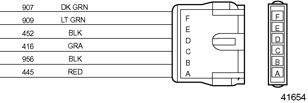
Also check pin F (throttle plate position) and pin C (sensor supply +5 VDC) in the throttle actuator connector (see Figure "Throttle Actuator Connector" ). If there is a short, repair or replace the wire(s), pins, and sockets.

Figure 2. Throttle Actuator Connector
- If PID 51, FMI 3, Flash Code 17 is still active, go to step .
- If PID 51, FMI 3, Flash Code 17 is no longer active, refer to "5.5.3 Verification" .
- Check wire 907 for a short to the +12V/+24V power supply. Check cavity R-1 in the ESH 30–pin connector and pin F (throttle plate position) in the throttle actuator connector. If there is a short, repair or replace the wire(s), pins, and sockets.
- If PID 51, FMI 3, Flash Code 17 is still active, replace the throttle (refer to "5.5.2 Throttle Assembly Procedure" ).
- If PID 51, FMI 3, Flash Code 17 is no longer active, refer to "5.5.3 Verification" .
Section 5.5.2
Throttle Assembly Procedure
Use the bolt tightening sequence and the throttle assembly procedure in the following sections when replacing the throttle. Refer to "5.5.2.1 Bolt Tightening Sequence" for the bolt tightening sequence and refer to "5.5.2.2 Throttle Assembly Procedure" for the throttle assembly procedure.
Section 5.5.2.1
Bolt Tightening Sequence
Loosen the bolts using the following sequence:
- Loosen the four bolts that attach the intake elbow to the rear of the throttle.
- Loosen the four bolts that attach the Mixer/PSV assembly to the front of the throttle
- Loosen the two bolts that attach the low pressure regulator to the intake elbow.
- Loosen the four bolts that attach the throttle to the throttle bracket.
Tighten all the bolts using the following sequence:
Note: Torque for all bolts is 34 N·m (25 ft·lb).
- Tighten the two bolts from the throttle bracket to the gear case.
- Tighten the one bolt from the throttle bracket to the cylinder head.
- Tighten the four bolts from the Mixer/PSV assembly to the throttle.
- Tighten the four bolts from the throttle to the inlet elbow.
- Tighten the two bolts from the IMPCO regulator.
- Tighten the two bolts from the throttle bracket to the inlet elbow.
- Tighten the four bolts from the bottom of the throttle bracket to the throttle.
Section 5.5.2.2
Throttle Assembly Procedure
Replace the throttle assembly as follows:
- Install the inlet elbow to the throttle flange with the flow arrow on the throttle pointing towards the inlet elbow.
- Install mixer assemble to opposite flange using the same gasket with four bolts but do not tighten.
- Attach the PSV and O-ring to the mixer with four Allen head screws but do not tighten.
- Lubricate O-rings used with fuel transfer tube with Lubriplate prior to assembly.
- Install O-rings to fuel transfer tube. Apply Teflon liquid pipe sealant to threads (see Figure "Assembling the Throttle" ).
- Thread fuel transfer tube into regulator and tighten.
Note: The fuel transfer tube must thread into the regulator just far enough so the O-ring seal doesn't bottom in the PSV valve and cut the seal when the regulator is bolted to the inlet elbow.
- Install the low pressure regulator and fuel transfer into the PSV. Bolt regulator to inlet elbow with two bolts but do not tighten (see Figure
"Assembling the Throttle"
).

1. Fuel Pressure Sensor
9. Washer
2. IMPCO Regulator
10. PSV O-ring
3. Elbow
11. Bolt
4. Balance Line
12. Mixer Assembly
5. Fuel Transfer Tube
13. Gasket
6. O-rings
14. Throttle Body
7. PSV
15. Elbow
8. Bolt
16. Air Temperature Sensor
Figure 3. Assembling the Throttle
- Install throttle, PSV, mixer and inlet elbow to engine positioning inlet hose over inlet elbow and inlet manifold. Rest the throttle on the throttle bracket (see Figure
"Throttle, Bracket, and Inlet Elbow Assembly — Series 50G"
).

1. Bolt
7. Air Temperature Sensor
2. Throttle Bracket
8. Elbow
3. Gear Case Cover-to-Bracket Bolts
9. Clamp
4. Throttle Actuator
10. Hose
5. Bushing
11. Inlet Manifold
6. Gasket
Figure 4. Throttle, Bracket, and Inlet Elbow Assembly — Series 50G
- Install four bolts through the throttle bracket into the bottom of the throttle and two bolts through the side of the throttle bracket into the inlet elbow but do not tighten.
- Tighten the four mixer to throttle bolts at 34 N·m (25 ft·lb) torque.
- Tighten the four throttle to inlet elbow bolts at 34 N·m (25 ft·lb) torque.
- Tighten the two bolts that hold the regulator to the inlet elbow and tighten the four screws that hold the PSV to the mixer.
- Adjust the two bolts through the throttle bracket to the inlet elbow and the four bolts through the bottom of the throttle bracket to the throttle alternatively to insure that there is no bind in the throttle. Torque the two brackets to the inlet elbow bolts at 34 N·m (25 ft·lb) and the four throttle mounting bolts at 34 N·m (25 ft·lb).
- If the code is still active, call Detroit Diesel Technical Service.
- If the code is no longer active, refer to "5.5.3 Verification" .
Section 5.5.3
Verification
Verify that troubleshooting was successful :
- Check the DDR to see if PID 51, FMI 3, Flash Code 17 is still active.
- If the code is still active, go to step 2.
- If the code is not active, troubleshooting is complete.
- Call Detroit Diesel Technical Service.
| Series 50G and 60G Troubleshooting Guide - 6SE482 |
| Generated on 10-13-2008 |