Section 8.6
DDEC IV Varible Pressure Output Devices
DDEC IV engines use two VPODs which control the VNT and EGR valve. During engine EGR operation, the VPODs provide modulated air pressure to the pneumatic actuators which change the position of the VNT vanes and the position of the EGR valve.
Section 8.6.1
Removal of Variable Pressure Output Devices
Removal steps are as follows:
- Disconnect the air line (7) fitting from the VPODs (6) and VNT actuator (8). See Figure
"VPODs Air Supply Lines and Related Parts"
.
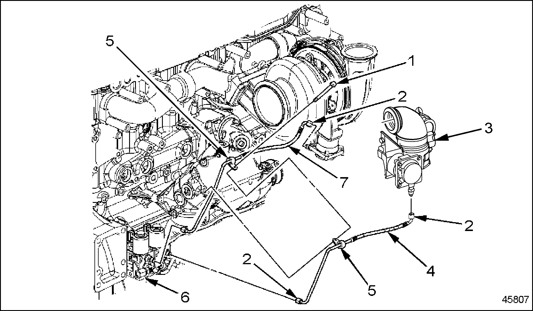
1. Bolt
3. EGR Valve Assembly
5. Clamps
7. Air Line
2. Air Line Fitting
4. Air Line
6. VPODs
8. VNT Actuator
Figure 1. VPODs Air Supply Lines and Related Parts
- Disconnect the air line (4) fittings from the EGR valve assembly (3) and the VPODs (6). See Figure "VPODs Air Supply Lines and Related Parts" .
- Disconnect the sensor harness (2) from the VPODs (4). See Figure
"VPODs and Related Parts"
.
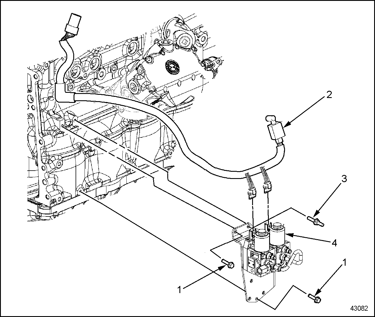
1. Bolt
3. Stud
2. Sensor Harness
4. VPODs
Figure 2. VPODs and Related Parts
- Remove the two bolts (1) and stud (3) that secure the VPODs (4) to the engine block. See Figure "VPODs and Related Parts" . Remove the VPODs.
Section 8.6.1.1
Inspection of Variable Pressure Output Devices
Inspection steps are as follows:
- To test the VPODs, refer to the Exhaust Gas Recirculation System Basic Checks Section
found in the DDEC V Single ECU Troubleshooting Guide
, 6SE497.
- If the VPOD is defective, replace the component.
- If the VPOD was not defective, reuse the component for installation.
- Visually check the sensor harness for damage.
- If the harness is damaged, repair as necessary and refer to the Wiring and Wires and Conduit and Loom sections found in DDEC IV Single ECU Troubleshooting Guide , 6SE497.
- If the harness is not damaged, reuse the harness for installation.
Section 8.6.2
Installation of Variable Pressure Output Devices
Installation steps are as follows:
- Align the VPODs (4) brackets to the engine block and secure with two bolts (1) and stud (3). See Figure
"VPODs and Related Parts"
. Torque the M10 bolt and M10 stud to 58-73 N·m (43-54 lb·ft) and the M8 bolt to 30-38 N·m (22-28 lb·ft).
1. Bolt
3. Stud
2. Sensor Harness
4. VPODs
Figure 3. VPODs and Related Parts
- Connect the sensor harness (2) to the VPODs (4). See Figure "VPODs and Related Parts" .
- Connect air line (7) fitting to the VPODs (6) and VNT actuator (8). See Figure
"VPODs Air Supply Lines and Related Parts"
.
1. Bolt
3. EGR Valve Assembly
5. Clamps
7. Air Line
2. Air Line Fitting
4. Air Line
6. VPODs
8. VNT Actuator
Figure 4. VPODs Air Supply Lines and Related Parts
- Connect air line (4) fittings to the EGR valve assembly (3) and to the VPODs (6). See Figure "VPODs Air Supply Lines and Related Parts" .
| Series 60 Service Manual - 6SE483 |
| Generated on 10-13-2008 |