Section 1.3
Rocker Arm Assembly
Two rocker arms are provided for each cylinder; one arm operates the exhaust valve and the other arm operates the intake valve. Each set of rocker arms pivot on a pedestal secured to the cylinder head. A spring plate secures the rocker arm to the pedestal.
The rocker arms are operated by the camshaft through lifters and push rods extending through the cylinder head.
Section 1.3.1
Repair or Replacement of Rocker Arm Assembly
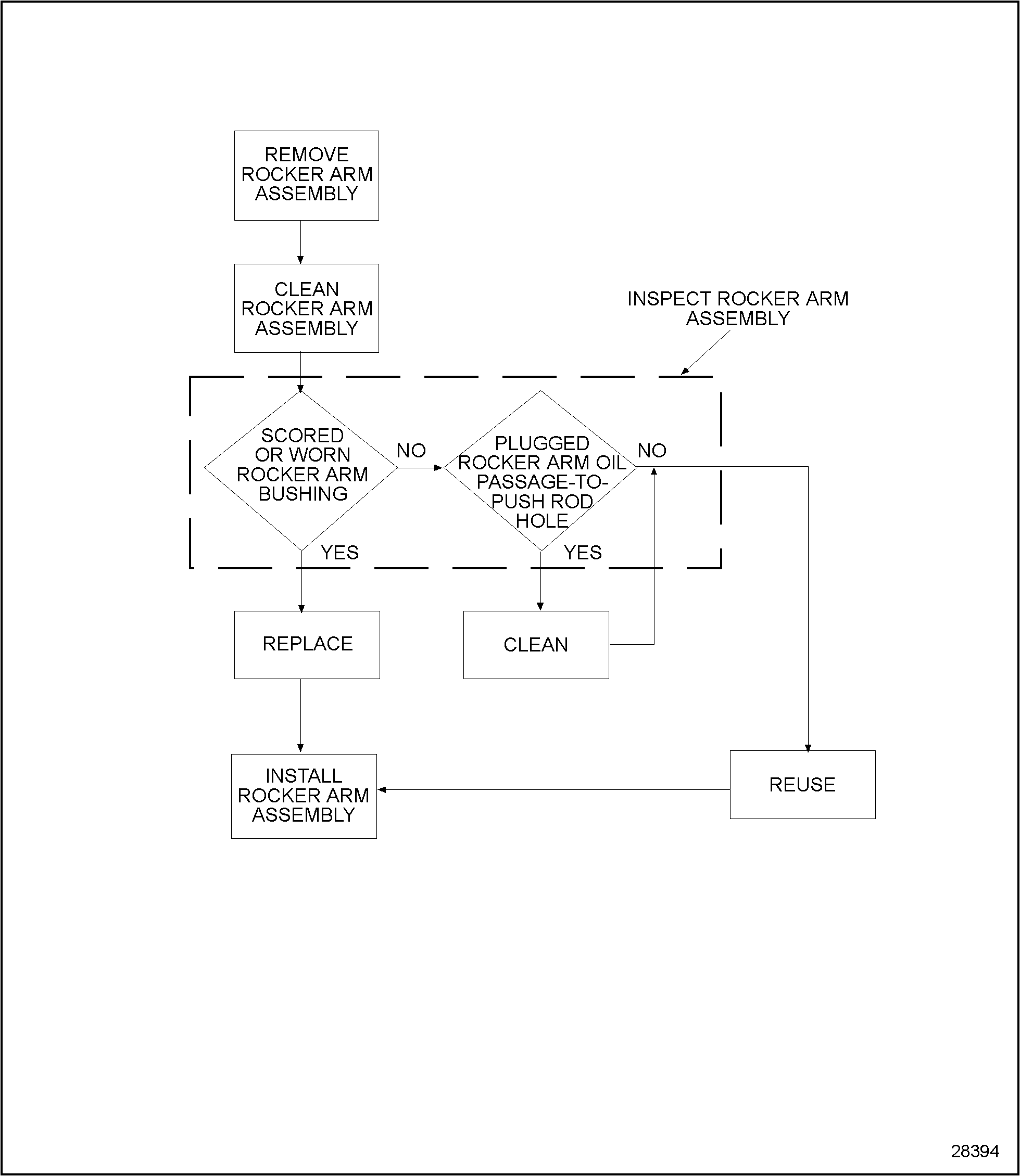
To determine if replacement or repair of the rocker arm assembly is necessary, perform the following procedure. See Figure "Flowchart for Replacement or Repair of Rocker Arm Assembly" .

Figure 1. Flowchart for Replacement or Repair of Rocker Arm Assembly
Section 1.3.2
Removal of Rocker Arm Assembly
Remove the rocker arm assembly as follows:
- Remove the rocker arm covers. Refer to "1.2.2 Removal of Front Rocker Cover" and refer to "1.2.4 Removal of Rear Rocker Cover" .
- Remove two rocker arm assembly nuts. See Figure
"Rocker Arm Assembly Components"
. Repeat step 2
for each cylinder head.

1.Cylinder Head
5.Spring Plate
2.Stud
6.Rocker Arm Nut
3.Exhaust Rocker Arm
7.Intake Rocker Arm
4.Rocker Arm Pedestal
Figure 2. Rocker Arm Assembly Components
- Remove rocker arm assembly. Repeat step 3 for each cylinder head.
- Remove push rod from the cylinder block. Repeat step 4 for each cylinder head.
Section 1.3.2.1
Cleaning of Rocker Arm Assembly
Clean the rocker arm assembly as follows:
- Remove dirt and debris from the rocker arm assembly surfaces.

To avoid personal injury when blow drying, wear adequate eye protection (safety glasses or face plate) and do not exceed 276 kPa (40 lb/in. 2 ) air pressure.
- Cleanse rocker arm assembly with clean fuel oil and blow dry with compressed air.
Section 1.3.2.2
Inspection of Rocker Arm Assembly
Inspect the rocker arm assembly as follows:
- Visually check inlet and exhaust rocker arm bushing for scoring or wear.
- If the rocker arm bushing is scored or worn, replace the component. Refer to "1.3.3 Installation of Rocker Arm Assembly" .
- If the rocker arm bushing is not scored or worn, proceed with step 2 of inspection.
- Visually check rocker arm oil passage-to-push rod hole.
- If the rocker arm oil passage-to-push rod hole is plugged, clean component as necessary. Refer to "1.3.3 Installation of Rocker Arm Assembly" .
- Refer to "1.3.3 Installation of Rocker Arm Assembly" .
Section 1.3.3
Installation of Rocker Arm Assembly
Install the rocker arm assembly as follows:
- Install push rod(s) to the cylinder block. Repeat step 1
for each cylinder head.
Note: Ensure that the push rod is centered and seated in the followers.
- Install rocker arm assembly. Repeat step 2 for each cylinder head.
- Install two rocker arm assembly nuts. Torque nuts to 26-27 N · m (19-20 lb · ft).
- Install the rocker covers. Refer to "1.2.3 Installation of Front Rocker Cover" and refer to "1.2.5 Installation of Rear Rocker Cover" .
- Run the engine to verify repairs.
| Series 638 Service Manual - 6SE648 |
| Generated on 10-13-2008 |