General Information
SCOPE AND USE OF THIS MANUAL
This manual contains complete instructions on operation, adjustment (tune-up), preventive maintenance, and repair (including complete overhaul) for the basic Series 50 Inline Diesel Engines. This manual was written primarily for persons servicing and overhauling the engine. In addition, this manual contains all of the instructions essential to the operators and users. Basic maintenance and overhaul procedures are common to all Series 50 Engines, and apply to all engine models.
This manual is divided into numbered sections. The first section covers the engine (less major assemblies). The following sections cover a complete system such as the fuel system, lubrication system, or air system. Each section is divided into subsections which contain complete maintenance and operating instructions for a specific engine subassembly. Each section begins with a table of contents. Pages and illustrations are numbered consecutively within each section.
Information can be located by using the table of contents at the front of the manual or the table of contents at the beginning of each section. Information on specific sub-assemblies or accessories within the major section is listed immediately following the section title.
SERVICE PARTS AVAILABILITY
Service parts are available throughout the world. A complete list of all Detroit Diesel Corporation (DDC) distributors and dealers is available in the Detroit Diesel Corporation World Wide Parts and Service Directory , 6SE280. This publication can be ordered from any authorized DDC distributor. The dealer must have the engine identification and model number (located on the engine block directly beneath the intake manifold) to fill a parts order.
CLEARANCE OF NEW PARTS AND WEAR LIMITS
New parts clearances apply only when all new parts are used at the point where the various specifications apply. This also applies to references within the text of the manual. The column entitled Limits must be qualified by the judgement of personnel responsible for installing new parts. For additional information, refer to the section entitled "Inspection" within this section. Refer to "Additional Information" , "Specifications, New Clearances, and Wear Limits" under "Specifications", for a listing of clearances of new parts and wear limits on used parts.
THE FOUR-CYCLE PRINCIPLE
The diesel engine is an internal combustion engine, in which the energy of burning fuel is converted into work in the cylinder of the engine. In the diesel engine, air alone is compressed in the cylinder, raising its temperature significantly. After the air has been compressed, a charge of fuel is sprayed into the cylinder and ignition is accomplished by the heat of compression. The four piston strokes of the cycle occur in the following order: intake, compression, power and exhaust. See Figure "The Four Stroke Cycle" .

Figure 1. The Four Stroke Cycle
Intake Stroke
During the intake stroke, the piston travels downward, the intake valves are open, and the exhaust valves are closed. The downstroke of the piston facilitates air from the intake manifold to enter the cylinder through the open intake valves. The turbocharger, by increasing the air pressure in the engine intake manifold, assures a full charge of air is available for the cylinder.
The intake charge consists of air only with no fuel mixture.
Compression Stroke
At the end of the intake stroke, the intake valves close and the piston starts upward on the compression stroke. The exhaust valves remain closed.
At the end of the compression stroke, the air in the combustion chamber has been compressed by the piston to occupy a space about one-fifteenth as great in volume as it occupied at the beginning of the stroke. Thus, the compression ratio is 15:1.
Compressing the air into a small space causes the temperature of that air to rise. Near the end of the compression stroke, the pressure of the air above the piston is approximately 3445 to 4134 kPa (500 to 600 lb/in.2 ) and the temperature of that air is approximately 538°C (1000°F). During the last part of the compression stroke and the early part of the power stroke, a small metered charge of fuel is injected into the combustion chamber.
Almost immediately after the fuel charge is injected into the combustion chamber, the fuel is ignited by the hot air and starts to burn, beginning the power stroke.
Power Stroke
During the power stroke, the piston travels downward and all intake and exhaust valves are closed.
As the fuel is added and burns, the gases get hotter, the pressure increases, pushing the piston downward and adding to crankshaft rotation.
Exhaust Stroke
During the exhaust stroke, the intake valves are closed; the exhaust valves are open, and the piston is on its upstroke.
The burned gases are forced out of the combustion chamber through the open exhaust valve port by the upward travel of the piston.
From the preceding description, it is apparent that the proper operation of the engine depends upon the two separate functions: first, compression for ignition, and second, that fuel be measured and injected into the compressed air in the cylinder in the proper quantity and at the proper time.
GENERAL DESCRIPTION
The Series 50® Diesel Engine described in this manual is a four-stroke cycle, high speed, diesel engine.
It uses an inline cast iron block and has a cast iron cylinder head that contains a single overhead camshaft. The camshaft actuates all the valves (two intake, two exhaust per cylinder), and operates the fuel injectors. The vertically aligned gear train, located at the front end of the engine in a gear case, contains drive gears for the lubricating oil pump, crankshaft, camshaft, air compressor drive, fuel pump drive, water pump and alternator accessory drives.
Each current engine is equipped with dual full flow oil filters, a bypass oil filter, an oil cooler, two fuel oil filters, a turbocharger and an electronic engine control system.
Full pressure lubrication is supplied to all main, connecting and camshaft bearings, and to other moving parts. A gear-type pump draws oil from the oil pan through a screen and delivers it to the oil filters. From the filter, a small portion of the oil is delivered directly to the turbocharger by an external oil line. The remainder of the oil flows to the oil cooler, or bypasses the cooler, and then enters a longitudinal oil gallery in the cylinder block where the supply divides. Part of the oil goes to the cylinder head where it feeds the camshaft bearings and rocker assemblies; part of the oil goes to the main bearings and connecting rod bearings via the drilled oil passages in the crankshaft. The remainder of the oil feeds the balance support where it lubricates the balance shaft bearings and is regulated. Drilled passages in the connecting rod feed oil to the piston pin and the inner surface of the piston crown.
Coolant is circulated through the engine by a centrifugal-type water pump. The cooling system, including the radiator, is a closed system. Heat is removed from the coolant by the radiator. Control of the engine temperature is accomplished by thermostats that regulate the flow of the coolant within the cooling system.
Fuel is drawn from the supply tank through the primary fuel filter by a gear-type fuel pump. From there, the fuel is forced through the secondary fuel filter and into the fuel inlet in the cylinder head and to the injectors. Excess fuel is returned, through a restricted fitting, to the supply tank through the outlet connecting line. Since the fuel is constantly circulating through the injectors, it serves to cool the injectors and to carry off any air in the fuel system.
Air is supplied by the turbocharger to the intake manifold and into the engine cylinders after passing through an air-to-air charge air cooler mounted ahead of the cooling system radiator. The charge air cooler cools the pressurized intake air charge coming from the turbocharger before it enters the intake manifold.
Engine starting may be provided by an electric or air starting motor energized by a storage battery or air pressure storage system. A battery charging alternator, with a suitable voltage regulator, serves to keep the battery charged.
The Series 50 Diesel Engine was designed to be electronically controlled. The Detroit Diesel Electronic Control (DDEC) system has evolved with the product.
DDEC II
DDEC II controls the timing and amount of fuel injected into each cylinder. The system monitors several engine sensors that send electrical signals to the main ECM. See Figure "Schematic Diagram of DDEC II" . Unlike DDEC I, the DDEC II ECM uses this information to actuate the Electronic Unit Injector (EUI) solenoids. The ECM also has the ability to limit or shut down the engine completely (depending on option selection) in the case of damaging engine conditions, such as low oil pressure, low coolant level, or high oil temperature.

Figure 2. Schematic Diagram of DDEC II
DDEC III
The DDEC III ECM receives electronic inputs from sensors on the engine and vehicle, and uses the information to control engine operation. It computes fuel timing and fuel quantity based upon predetermined calibration tables in its memory.
Fuel is delivered to the cylinders by the EUI solenoids, which are cam-driven to provide the mechanical input for pressurization of the fuel. The ECM controls solenoid operated valves in the EUIs to provide precise fuel delivery. See Figure "Schematic Diagram of DDEC III" .
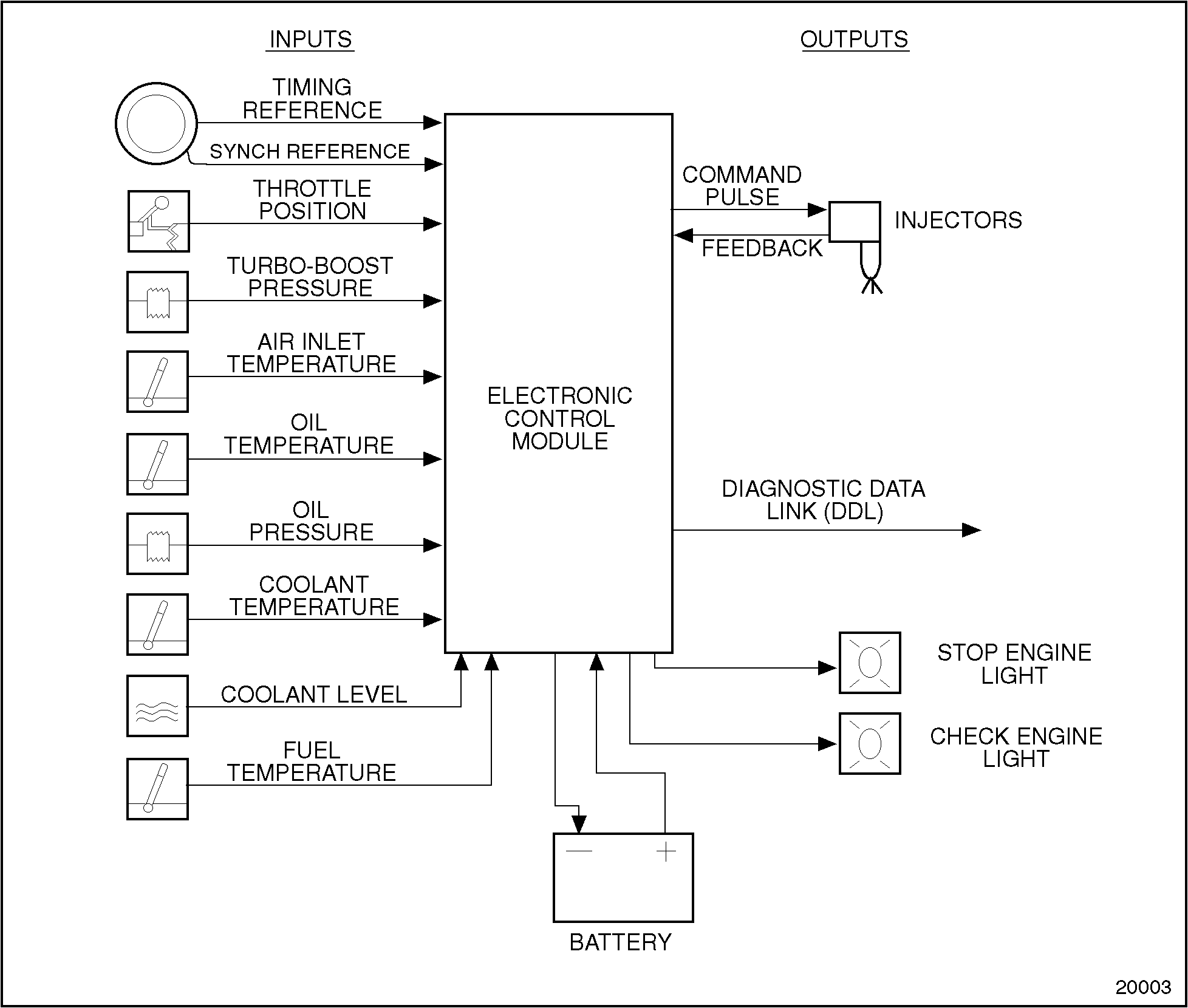
Figure 3. Schematic Diagram of DDEC III
Portable equipment facilitates access to diagnostic capabilities of DDEC. The Diagnostic Data Reader (DDR) requests and receives engine data and diagnostic codes. This equipment provides many unique capabilities including cylinder cutout, parameter vs. engine speed (or time), printer output, and data snapshot. The DDR also provides limited programming capability.
DDEC III (Series 50G)
The DDEC III ECM receives electronic inputs from sensors on the engine and vehicle, and uses the information to control engine operation.
Natural gas is delivered to the cylinders by the G.F.I compuvalve on a high pressure fuel system. Fuel is controlled by DDEC on the low pressure system. See Figure "Schematic Diagram of DDEC III (Series 50G)" .
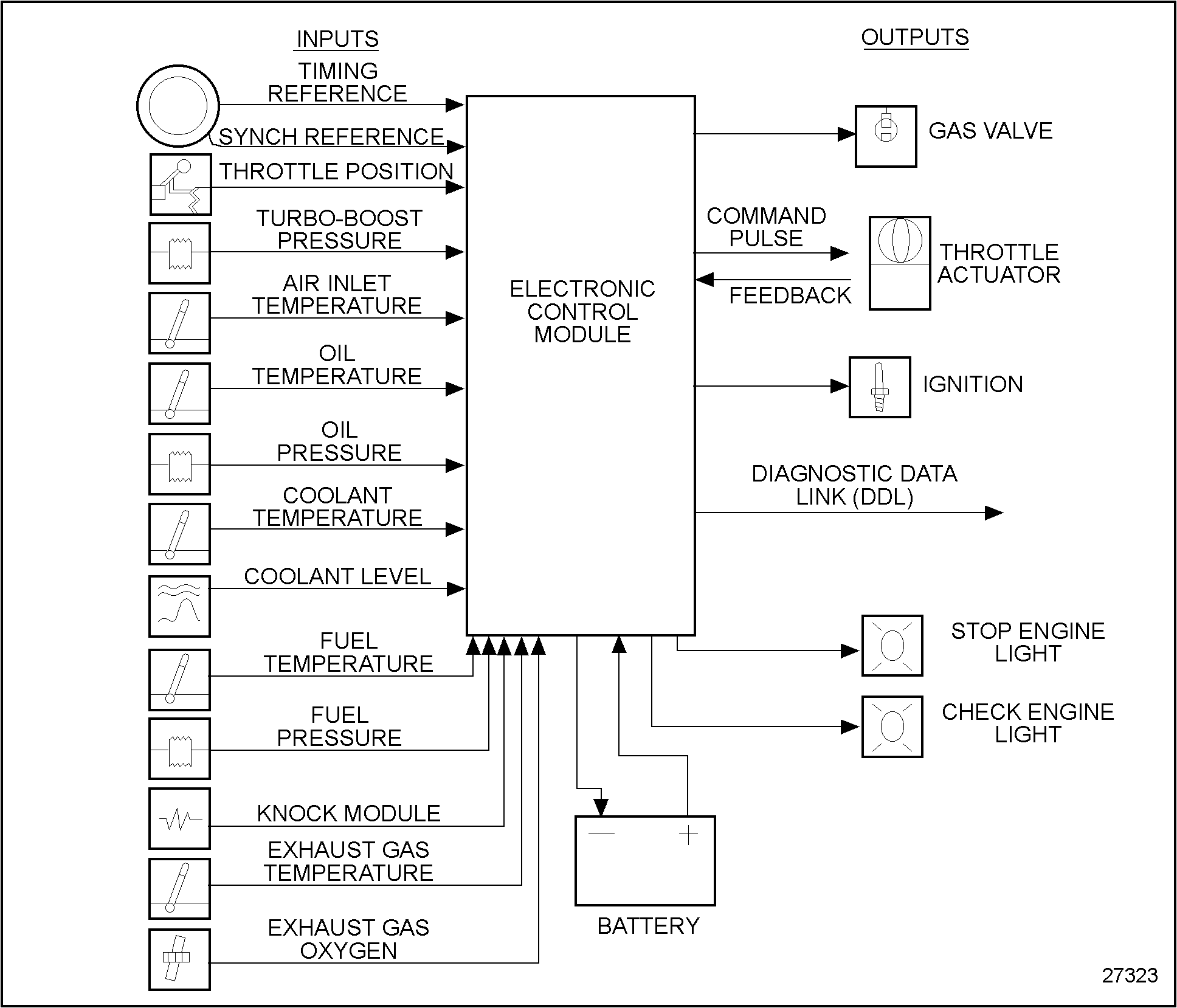
Figure 4. Schematic Diagram of DDEC III (Series 50G)
Portable equipment facilitates access to diagnostic capabilities of DDEC. The Diagnostic Data Reader (DDR) requests and receives engine data and diagnostic codes. This equipment provides many unique capabilities including cylinder cutout, parameter vs. engine speed (or time), printer output, and data snapshot. The DDR also provides limited programming capability.
GENERAL SPECIFICATIONS
The general specifications for the Series 50 Engine are listed in Table "General Specifications for the Series 50 Engine" . See Figure "Cylinder Designation and Firing Order" for the cylinder designation and firing order.
|
General Specifications |
Engine Family |
|
Total Displacement (L) |
8.5 |
|
Total Displacement (in.3 ) |
518 |
|
Type |
Four-cycle |
|
Number of Cylinders |
4 |
|
Bore (in.) |
5.12 |
|
Bore (mm) |
130 |
|
Stroke (in.) |
6.30 |
|
Stroke (mm) |
160 |
|
Compression Ratio |
15.0:1 |
|
Number of Main Bearings |
5 |
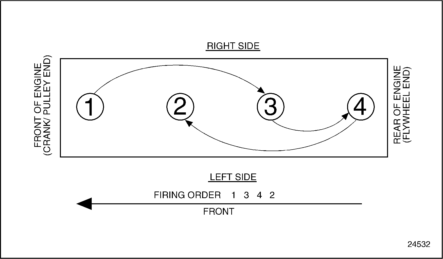
Figure 5. Cylinder Designation and Firing Order
GENERAL SPECIFICATIONS FOR THE SERIES 50G ENGINE
The general specifications for the Series 50G Engine are listed in Table "General Specifications for the Series 50G Engine" . See Figure "Cylinder Designation and Firing Order for the Series 50G Engine" for cylinder designation and firing order.
|
General Description |
Specification |
|
Total Displacement (L) |
8.5 |
|
Total Displacement (in.3 ) |
518 |
|
Type |
Four-cycle |
|
Number of Cylinders |
4 |
|
Bore (in.) |
5.12 |
|
Bore (mm) |
130 |
|
Stroke (in.) |
6.30 |
|
Stroke (mm) |
160 |
|
Compression Ratio |
10:1 |
|
Number of Main Bearings |
5 |
Figure 6. Cylinder Designation and Firing Order for the Series 50G Engine
ENGINE MODEL, SERIAL NUMBER AND OPTION LABEL
The engine serial and model numbers are stamped on the cylinder block. See Figure "Location of Engine Serial and Model Number on Block" . A guide to the meaning of the model number digits is listed in Table "Model Number Description for Series 50" .
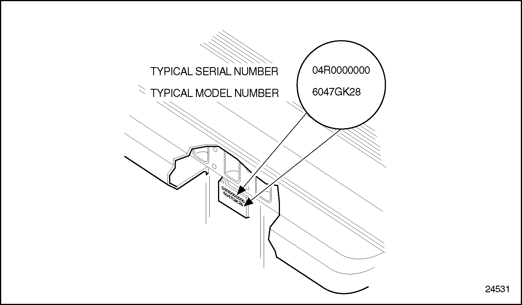
Figure 7. Location of Engine Serial and Model Number on Block
|
Digit |
Value |
Meaning |
|
1 |
6 |
Series 50 Engine |
|
2 & 3 |
04 |
Four Cylinders |
|
4 |
7 |
Automotive Application |
|
5 |
G |
8.5 L Displacement |
|
6 |
U |
DDEC II Engine Control |
|
6 |
K |
DDEC III Engine Control |
|
7 & 8 |
28 |
" T" Drive |
|
7 & 8 |
26 |
" V" Drive |
ENGINE MODEL, SERIAL NUMBER AND OPTION LABEL (SERIES 50G)
The engine serial and model numbers are stamped on the cylinder block. See Figure "Location of Engine Serial and Model Number on Block (Series 50G)" . The model number description for the Series 50G is listed in Table "Model Number Description for Series 50G" .
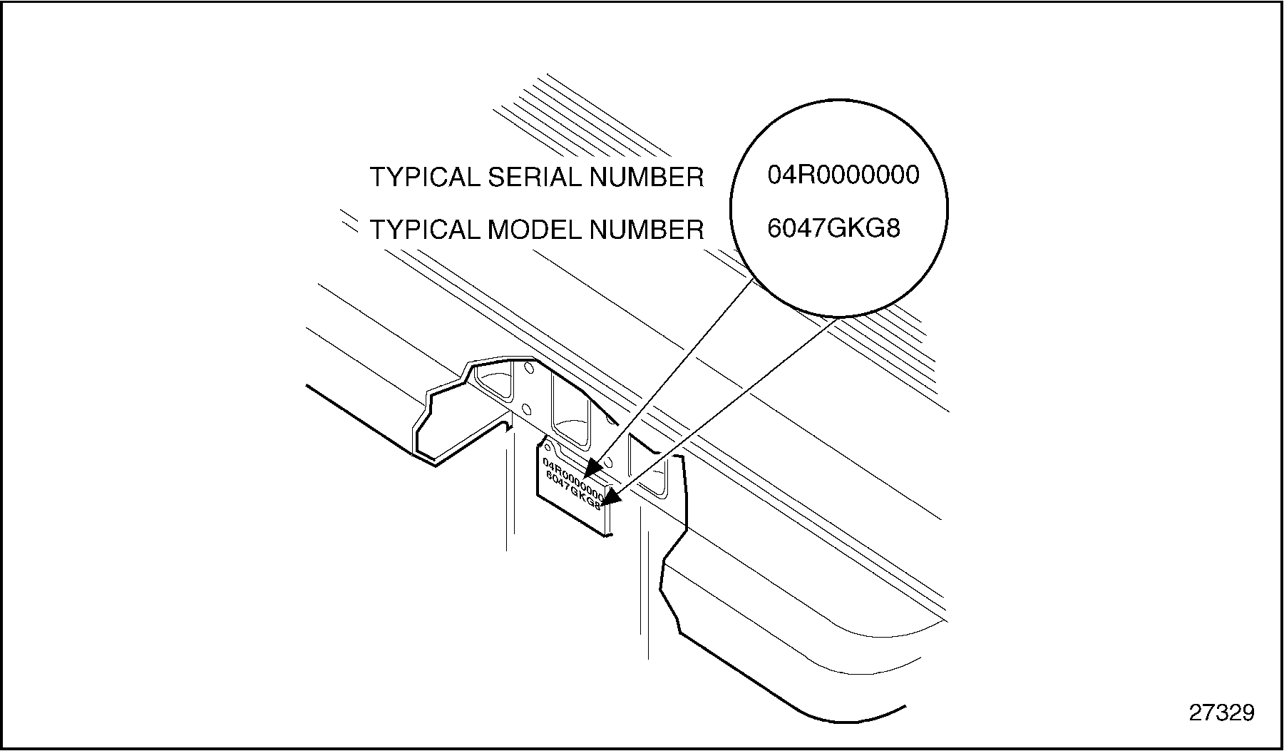
Figure 8. Location of Engine Serial and Model Number on Block (Series 50G)
|
Digit |
Value |
Meaning |
|
1 |
6 |
Series 50 Engine |
|
2 & 3 |
04 |
Four Cylinders |
|
4 |
7 |
Automotive Application |
|
5 |
G |
8.5 L Displacement |
|
6 |
K |
DDEC III Engine Control |
|
7 |
G |
Alternate Fuel Engine |
|
8 |
8 |
Customer Designation |
Option labels attached to the valve rocker cover contain the engine serial and model numbers and list any optional equipment used on the engine. See Figure "Rocker Cover with Option Label" .

Figure 9. Rocker Cover with Option Label
With any order for parts, the engine model number with serial number should be given. In addition, if a type number is shown on the option plate covering the equipment required, this number should also be included on the parts order.
All groups or parts used on a unit are standard for the engine model unless otherwise listed on the option plate.
REPLACING AND REPAIRING
In many cases, a service person is justified in replacing parts with new material rather than attempting repair. However, there are times when a slight amount of reworking or reconditioning may save a customer considerable added expense. Exchange assemblies such as injectors, fuel pumps, water pumps and turbochargers are desirable service items.
Various factors such as the type of operation of the engine, hours in service and the next overhaul period must be considered when determining whether new parts are installed or used parts are reconditioned to provide trouble-free operation.
For convenience and logical order in disassembly and assembly, the various subassemblies and other related parts mounted on the cylinder block will be treated as separate items in the various sections of the manual.
DISASSEMBLY
A service person can be severely injured if caught in pulleys, belts or the fan of an engine that is accidentally started. To avoid such a misfortune, take the following precautions before starting to work on an engine.
|
PERSONAL INJURY |
|
To avoid injury from accidental engine startup while servicing the engine, disconnect/disable the starting system. |
|
PERSONAL INJURY |
|
To avoid injury from the sudden release of a high-pressure hose connection, wear a face shield or goggles. Bleed the air from the air starter system before disconnecting the air supply hose. |
Before any major disassembly, the engine must be drained of lubricating oil, coolant and fuel.
To perform a major overhaul or other extensive repairs, the complete engine assembly, after removal from the engine base and drive mechanism, should be mounted on an engine overhaul stand; then the various subassemblies should be removed from the engine. When only a few items need replacement, it is not always necessary to mount the engine on an overhaul stand.
Parts removed from an individual engine should be kept together so they will be available for inspection and assembly. Those items having machined faces, which might be easily damaged by steel or concrete, should be stored on suitable wooden racks or blocks, or a parts dolly.
CLEANING
Before removing any of the subassemblies from the engine (but after removal of the electrical equipment), the exterior of the engine should be thoroughly cleaned.
NOTICE: |
|
The Series 50 Engine is equipped with various sensors and other electronic components which may be damaged if subjected to the high temperatures in a solvent tank. Do not immerse any electrical components in a solvent tank. Care should be taken to ensure that all electronic components are removed from the various engine assemblies before they are immersed in a solvent tank. Refer to "2.10 Electronic Engine Control" for a description of these components. |
Then, after each subassembly is removed and disassembled, the individual parts should be cleaned. Thorough cleaning of each part is absolutely necessary before it can be satisfactorily inspected. Various items of equipment needed for general cleaning are listed below.
The cleaning procedure used for all ordinary cast iron parts is the same as the following cylinder block cleaning procedure. Any special cleaning procedures will be mentioned when required.
Remove cylinder liners with the cylinder liner removal tool, J 35791 , before putting the block in cleaning or descaling baths, to avoid trapping cleaning agents in block liner seating bores.
After stripping and before removing the cylinder block from the overhaul stand for cleaning and inspection, install the two metric eye bolts, J 35595 , into head bolt holes at each end of the cylinder block.
Remove all oil and water gallery and weep hole plugs to allow the cleaning solution to enter the inside of the oil and water passages.
- Using two metric eye bolts, J 35595 installed in the head bolt holes at opposite ends of the block, and with a suitable lifting device and spreader bar, immerse and agitate the block in a hot bath of a commercial, heavy-duty alkaline solution.
- Wash the block in hot water or steam clean it to remove the alkaline solution.
- If the water jackets are heavily scaled, proceed as follows:
- Agitate the block in a bath of inhibited phosphoric acid.
- Allow the block to remain in the acid bath until the bubbling action stops (approximately 30 minutes).
- Lift the block, drain it and re-immerse it in the same acid solution for 10 more minutes. Repeat until all scale is removed from the water jacket area.
- Rinse the block in clear, hot water to remove the acid solution.
- Neutralize the acid that may cling to the casting by immersing the block in an alkaline bath.
- Wash the block in clean water or steam clean it.

EYE INJURY
To avoid injury from flying debris when using compressed air, wear adequate eye protection (face shield or safety goggles) and do not exceed 276 kPa (40 psi) air pressure.
- Dry the cylinder block with compressed air.
- Blow out all of the bolt holes and passages with compressed air.
Note: The above cleaning procedure may be used on all ordinary cast iron and steel parts for the engine. Aluminum parts, such as flywheel housing, air intake manifold, oil filter adaptor and the camshaft gear access cover should NOT be cleaned in this manner. Mention will be made of special procedures when necessary.
- Be certain that all water passages and oil galleries have been thoroughly cleaned. After the cylinder block has been thoroughly cleaned and dried, install weep hole plugs and precoated pipe plugs. Install new cup plugs using a coating of good grade non-hardening sealant such as Loctite 620 or equivalent.
Steam Cleaning
A steam cleaner is a necessary item in a large shop and is most useful for removing heavy accumulations of grease and dirt from the exterior of the engine and its subassemblies.
Solvent Tank Cleaning
A tank of sufficient size to accommodate the largest part that will require cleaning (usually the cylinder block) should be provided and provisions made for heating the cleaning solution.
Fill the tank with a commercial heavy-duty solvent that is heated to 52°C (125°F). Lower large parts directly into the tank with a hoist. Place small parts in a wire mesh basket and lower them into the tank. Immerse the parts long enough to loosen all of the grease and dirt.
Note: Aluminum or plastic parts such as the flywheel housing, fuel pump drive, air intake manifold, oil filter adaptor, camshaft gear access cover, oil pan or rocker covers, should not be cleaned in this manner.
Chlorinated solvents such as 1,1,1 trichloroethane have been identified by the EPA (Environmental Protection Agency) as possessing ozone-depleting properties. Detroit Diesel believes that a prudent environmental approach to the use of 1,1,1 trichloroethane should be taken. Therefore, Detroit Diesel recommends replacing 1,1,1 trichloroethane with Tech Solv 340 branded solvent wherever the former solvent was used.
Tech Solv 340 is a petroleum-based solvent which contains no chlorinated or fluorinated compounds, has a controlled evaporation rate, leaves no residue, is odorless, has a high flash point, and provides outstanding cleaning. To enhance its cleaning and drying properties, it may be heated to 525°C (977°F). Spills can be cleaned up with commercially available oil absorbents, and conventional waste treatment methods for petroleum-base products can be used when disposing of this product.
Tech Solv 340 is manufactured by and available from the following supplier:
Chemical Technologies, Inc.*
1610 Clara Street
Jackson, MI 94203
Telephone: 800-688-8262
FAX: 517-782-2448
* We believe this source and their Tech Solv 340 solvent to be reliable. There may be other manufacturers of solvents that replace 1,1,1 trichloroethylene. Detroit Diesel does not endorse, indicate any preference for, or assume any responsibility for the solvents from these firms or for any such products that may be available from other sources.
Rinsing Bath
Provide another tank of similar size containing hot water for rinsing the parts.
Drying
Parts may be dried with compressed air. The heat from the hot tanks will quite frequently complete drying of the parts without the use of compressed air.
|
EYE INJURY |
|
To avoid injury from flying debris when using compressed air, wear adequate eye protection (face shield or safety goggles) and do not exceed 276 kPa (40 psi) air pressure. |
Rust Preventive
If parts are not to be used immediately after cleaning, dip them in a suitable rust preventive compound. The rust preventive compound should be removed before installing the parts in an engine.
Gasket Eliminator Removal
The gasket eliminator used on numerous mating surface joints in the Series 50 engine results in a very thin film that must be removed from both surfaces prior to reassembly. As many of the surfaces are aluminum and/or dimensionally critical, conventional scraping methods, or the use of emery cloth for removing gasket eliminator is not recommended.
Four-inch, 3M Scotch-Brite Surface Conditioning Discs, used with an electric or air powered hand drill (with a speed of 15,000-18,000 r/min), have proven successful in removing the gasket eliminator without damaging the mating surfaces of engine parts. See Figure "Gasket Eliminator Removal" .

Figure 10. Gasket Eliminator Removal
A coarse pad, J 36571-3 part of tool set J 36571 , (3M #07450, brown color), is suitable for steel surfaces. A medium pad, J 36571-2 part of tool set J 36571 (3M #07451, maroon color), is recommended for aluminum surfaces.
The pads are easily interchangeable using disc holder, J 36571-1 part of tool set J 36571 (3M #07492). See Figure "Scotch-Brite Surface Conditioning Disc Installation, J 36571 " .

Figure 11. Scotch-Brite Surface Conditioning Disc Installation, J 36571
INSPECTION
The purpose of parts inspection is to determine which parts can be used and which must be replaced. Although the engine overhaul specifications given throughout the text will aid in determining which parts should be replaced, considerable judgment must be exercised by the inspector. The guiding factors in determining the usability of worn parts, that are otherwise in good condition, is the clearance between the mating parts and the rate of wear on each of the parts. If it is determined that the rate of wear will maintain the clearances within the specified maximum allowed until the next overhaul period, the reinstallation of used parts may be justified. Rate of wear of a part is determined by dividing the amount the part has worn by the hours it has operated.
Many service replacement parts are available in various undersize or oversizes as well as standard sizes. Also, service kits for reconditioning certain parts and service sets that include all of the parts necessary to complete a particular repair job are available.
A complete discussion of the proper methods of precision measuring and inspection are outside the scope of this manual. However, every shop should be equipped with standard gages, such as dial bore gages, dial indicators, and inside and outside micrometers.
In addition to measuring the used parts after cleaning, the parts should be carefully inspected for cracks, scoring, chipping and other detrimental conditions.
SAFETY PRECAUTIONS
The following safety measures are essential when working on the Series 50 engine.
|
PERSONAL INJURY |
|
Diesel engine exhaust and some of its constituents are known to the State of California to cause cancer, birth defects, and other reproductive harm.
|
Stands
Safety stands are required in conjunction with hydraulic jacks or hoists. Do not rely on either the jack or the hoist to carry the load. When lifting an engine, be sure the lifting device is fastened securely. Be sure the item to be lifted does not exceed the capacity of the lifting device.
Glasses
Select appropriate safety glasses for the job. It is especially important to wear safety glasses when using tools such as hammers, chisels, pullers or punches.
Welding
Wear welding goggles and gloves when welding or using an acetylene torch. Ensure that a metal shield separates the acetylene and oxygen that must be chained to a cart.
|
PERSONAL INJURY |
|
To avoid injury from arc welding, gas welding, or cutting, wear required safety equipment such as an arc welder's face plate or gas welder's goggles, welding gloves, protective apron, long sleeve shirt, head protection, and safety shoes. Always perform welding or cutting operations in a well ventilated area. The gas in oxygen/acetylene cylinders used in gas welding and cutting is under high pressure. If a cylinder should fall due to careless handling, the gage end could strike an obstruction and fracture, resulting in a gas leak leading to fire or an explosion. If a cylinder should fall resulting in the gage end breaking off, the sudden release of cylinder pressure will turn the cylinder into a dangerous projectile. Observe the following precautions when using oxygen/acetylene gas cylinders:
|
Work Place
Organize your work area and keep it clean. Eliminate the possibility of a fall by:
- Wiping up oil spills
- Keeping tools and parts off the floor
After servicing or adjusting the engine:
- Reinstall all safety devices, guards or shields
- Ensure that all tools and servicing equipment are removed from the engine
Clothing
Safe work clothing fits and is in good repair. Work shoes are sturdy and rough-soled. Bare feet, sandals or sneakers are not acceptable foot wear when adjusting and/or servicing an engine.
|
PERSONAL INJURY |
|
To avoid injury when working near or on an operating engine, remove loose items of clothing and jewelry. Tie back or contain long hair that could be caught in any moving part causing injury. |
Power Tools
Never use defective portable power tools.
|
ELECTRICAL SHOCK |
|
To avoid injury from electrical shock, follow OEM furnished operating instructions prior to usage. |
Air
Recommendations regarding the use of air are indicated throughout the manual. Too much air can rupture or in some other way damage a component and create a hazardous situation that can lead to personal injury. Use only approved air blow guns that do not exceed 276 kPa (40 lb/in.2 ). Be sure to wear safety glasses or goggles. Use proper shielding to protect everyone in the work area.
|
EYE INJURY |
|
To avoid injury from flying debris when using compressed air, wear adequate eye protection (face shield or safety goggles) and do not exceed 276 kPa (40 psi) air pressure. |
Fuel Lines
Remove fuel lines as an assembly. Do not remove fuel lines individually. Avoid getting fuel injection lines mixed up.
Fluids and Pressure
Be extremely careful when dealing with fluids under pressure. Fluids under pressure can have enough force to penetrate the skin. These fluids can infect a minor cut or opening in the skin. If injured by escaping fluid, see a doctor at once. Serious infection or reaction can result without immediate medical treatment.
|
PERSONAL INJURY |
|
To avoid injury from penetrating fluids, do not put your hands in front of fluid under pressure. Fluids under pressure can penetrate skin and clothing. |
Fuel
Keep the hose and nozzle or the funnel and container in contact with the metal of the fuel tank when refueling.
|
PERSONAL INJURY |
|
To avoid injury from penetrating fluids, do not put your hands in front of fluid under pressure. Fluids under pressure can penetrate skin and clothing. |
|
PERSONAL INJURY |
|
To avoid injury from fuel spills, do not overfill the fuel tank. |
This will avoid the possibility of an electric spark igniting the fuel.
|
FIRE |
|
To avoid injury from fire, keep all potential ignition sources away from diesel fuel, including open flames, sparks, and electrical resistance heating elements. Do not smoke when refueling. |
Batteries
Electrical storage batteries emit highly flammable hydrogen gas when charging and continue to do so for some time after receiving a steady charge.
|
Battery Explosion and Acid Burn |
|
To avoid injury from battery explosion or contact with battery acid, work in a well ventilated area, wear protective clothing, and avoid sparks or flames near the battery. If you come in contact with battery acid:
|
Always disconnect the battery cable before working on the electrical system.
|
PERSONAL INJURY |
|
To avoid injury from accidental engine startup while servicing the engine, disconnect/disable the starting system. |
|
PERSONAL INJURY |
|
To avoid injury from the sudden release of a high-pressure hose connection, wear a face shield or goggles. Bleed the air from the air starter system before disconnecting the air supply hose. |
Disconnect the batteries or disable an air starter when working on the engine to prevent accidental starting.
Fire
Keep a charged fire extinguisher within reach. Be sure you have the correct type of extinguisher for the situation.
Cleaning Agent
Avoid the use of carbon tetrachloride as a cleaning agent because of the harmful vapors that it releases. Be sure the work area is adequately ventilated. Use protective gloves, goggles or face shield, and apron.
Exercise caution against burns when using oxalic acid to clean the cooling passages of the engine.
Working on a Running Engine
When working on an engine that is running, accidental contact with the hot exhaust manifold can cause severe burns. Remain alert to the location of the rotating fan, pulleys and belts. Avoid making contact across the two terminals of a battery which can result in severe arcing, or battery explosion.
|
PERSONAL INJURY |
|
Diesel engine exhaust and some of its constituents are known to the State of California to cause cancer, birth defects, and other reproductive harm.
|
|
PERSONAL INJURY |
|
To avoid injury from contact with rotating parts when an engine is operating with the air inlet piping removed, install an air inlet screen shield over the turbocharger air inlet. The shield prevents contact with rotating parts. |
|
PERSONAL INJURY |
|
To avoid injury when working near or on an operating engine equipped with an hydraulic clutch fan:
|
|
PERSONAL INJURY |
|
To avoid injury when working near or on an operating engine equipped with an hydraulic clutch fan, remove loose items of clothing and jewelry. Tie back or contain long hair that could be caught in any moving part causing injury. The hydraulic fan may start without warning. |
|
ELECTRICAL SHOCK |
|
To avoid injury from electrical shock, do not touch battery terminals, alternator terminals, or wiring cables while the engine is operating. |
|
PERSONAL INJURY |
|
To avoid injury when working near or on an operating engine equipped with electric fans, remove loose items of clothing and jewelry. Tie back or contain long hair that could be caught in any moving part causing injury. Electric fans may start without warning. |
|
PERSONAL INJURY |
|
To avoid injury when working near or on an operating engine, remove loose items of clothing and jewelry. Tie back or contain long hair that could be caught in any moving part causing injury. |
Start Attempts
Avoid excessive injection of ether into the series 50 engine during start attempts. Follow the instructions on the container or by the manufacturer of the starting aid.
|
FIRE, EXPLOSION AND TOXICITY |
|
To avoid injury from flames, explosion, and toxicants when using ether, the following precautions must be taken:
|
Turbocharger Compressor Inlet Shield
A turbocharger compressor inlet shield, J 26554-A is available and must be used anytime the engine is operated with the air inlet piping removed. See Figure "Turbocharger Compressor Inlet Shield, J 26554-A " . The shield helps to prevent foreign objects from entering and damaging the turbocharger and will prevent the mechanic from accidentally touching the turbocharger impeller. The use of this shield does NOT preclude any other safety practices contained in this manual. See Figure "Turbocharger Compressor Inlet Shield, Series 50G" for Series 50G.
|
PERSONAL INJURY |
|
To avoid injury from contact with rotating parts when an engine is operating with the air inlet piping removed, install an air inlet screen shield over the turbocharger air inlet. The shield prevents contact with rotating parts. |

Figure 12. Turbocharger Compressor Inlet Shield, J 26554-A
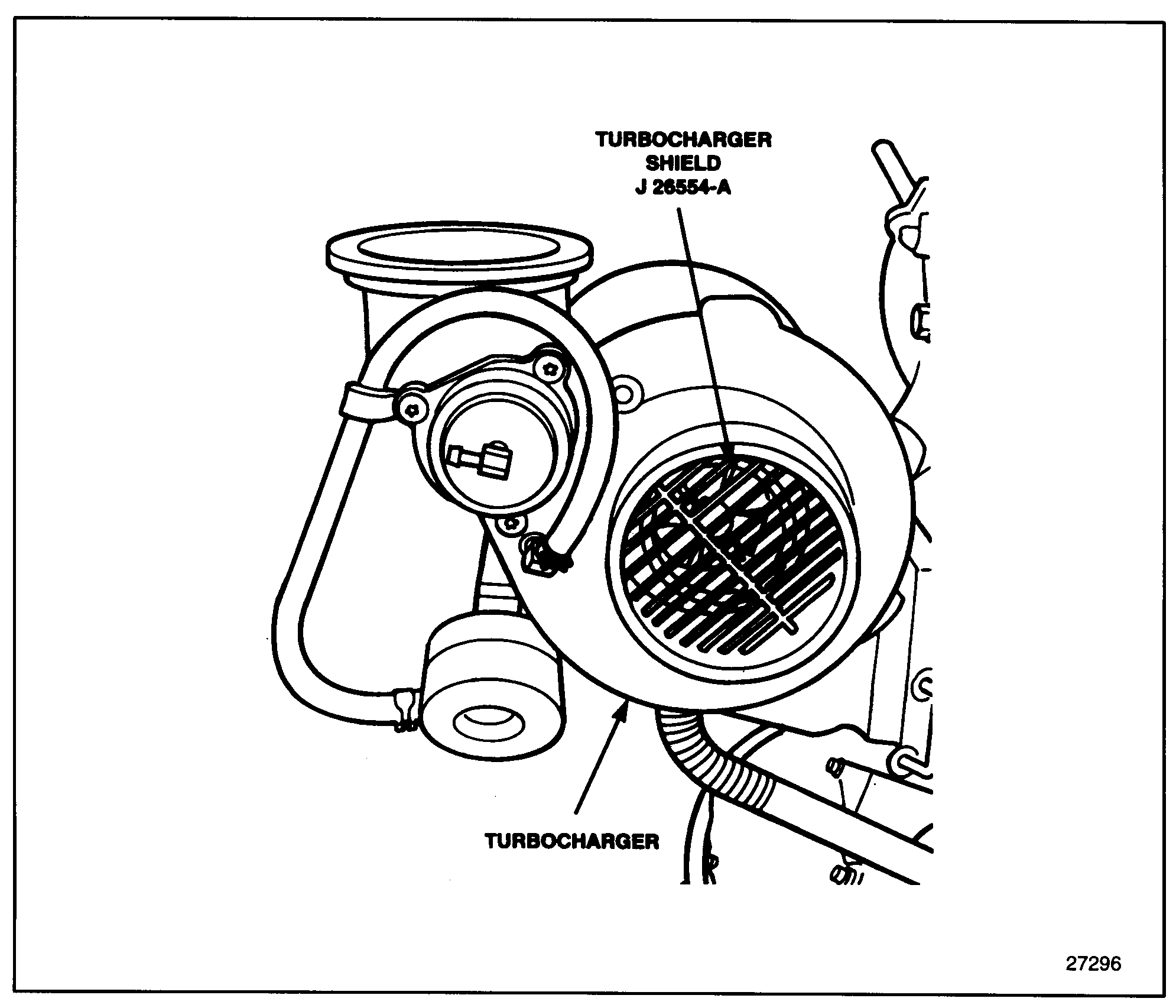
Figure 13. Turbocharger Compressor Inlet Shield, Series 50G
FLUOROELASTOMER (VITON) CAUTION
Under normal design conditions, fluoroelastomer (VITON ) parts, such as O-rings and seals, are perfectly safe to handle. However, a potential hazard may occur if these components are raised to a temperature above 316°C (600°F), such as during a cylinder failure or engine fire. At temperatures above 316°C (600°F) fluoroelastomer will decompose (indicated by charring or the appearance of a black, sticky mass) and produce hydrofluoric acid. This is extremely corrosive and, if touched by bare skin, may cause severe burns, sometimes with symptoms delayed for several hours.
|
CHEMICAL BURNS |
|
To avoid injury from chemical burns, wear a face shield and neoprene or PVC gloves when handling fluoroelastomer O-rings or seals that have been degraded by excessive heat. Discard gloves after handling degraded fluoroelastomer parts. |
ENGINE VIEWS AND ELECTRONIC CONTROL MODULE MOUNTING
With the introduction of the improved mounting of the Series 50 electronic control module (ECM) to horizontal position, it was necessary to modify the 50 DN alternator mounting. This modification provides for longer bracket support bolted directly to the engine block from the alternator which reduces vibration. Also, this new position will provide for easier servicing and reduces the potential for moisture to enter the wiring harness connections. This change went into effect in December 1995.
The former alternator support bracket is not required with the current block and the bracket support are not interchangeable with the improved mounting. This change does not affect the rear-mounted ECM.
The current cylinder block assembly (23519301) is interchangeable with the former cylinder block assembly (23511361) with the only change being the addition of three bosses and a mounting pad. A service kit (23519302) was released to allow the current block to be used in place of former blocks for service. The current block service kit now contains stud and spacer (23519297) to allow for the mounting of the ECM in the vertical position. Service kit (23519302) will supersede former service kit (23517607).
For Series 50 engine views, see Figure "Engine Views Series 50" .
For Series 50G engine views, see Figure "Engine Views Series 50G" .

Figure 14. Engine Views Series 50

Figure 15. Engine Views Series 50G
ENGLISH TO METRIC CONVERSION
Listed in Table "English to Metric Conversion" are the English to metric conversions.
|
Description |
By |
Unit of Measurement |
|
Multiply Leng
|