Section 6.15
SID 232, FMI 1, Flash Code 46, Sensor Supply Voltage Low
The sensor supply voltage is below normal range.
Section 6.15.1
Troubleshooting SID 232, FMI 1, Flash Code 46, Sensor Supply Voltage Low
Troubleshoot as follows:
NOTICE: |
|
To avoid damage to the harness and connectors when disconnecting harness connectors, ensure the pulling force is applied to the connectors and not to the wires extending from the connectors. |
- Check wire 916 (red and black, 5 VDC sensor supply) and T-splice wire 749 (yellow, sensor supply diagnostic) for a faulty 51 kΩ resistor at cavities A-3 (wire 916) and D-3 (wire 749) in the Vehicle Interface Harness (VIH) 30–pin connector (see Figure
"Vehicle Interface Harness 30–pin Connector"
). Ensure the resistor is a metal film (not carbon) precision resistor with 0 to 1% accuracy and 0.5 Watt or higher rating. If not, replace with proper resistor and repair the wires.

Figure 1. Vehicle Interface Harness 30–pin Connector
- If code is still active, go to step 2.
- If the code is no longer active, refer to "6.15.2 Verification" .
- Check wire 909 (light green, PWM No. 2) for a short to wire 416 (gray, 5 VDC sensor supply) at cavities Y-1 (wire 909) and W-1 (wire 416) in the Engine Sensor Harness (ESH) 30–pin connector (see Figure
"Engine Sensor Harness 30–pin Connector"
) and pin E (wire 909) in the throttle actuator connector (see Figure
"Throttle Actuator Connector"
). If there is a short, repair or replace the wire(s), pins, and sockets.
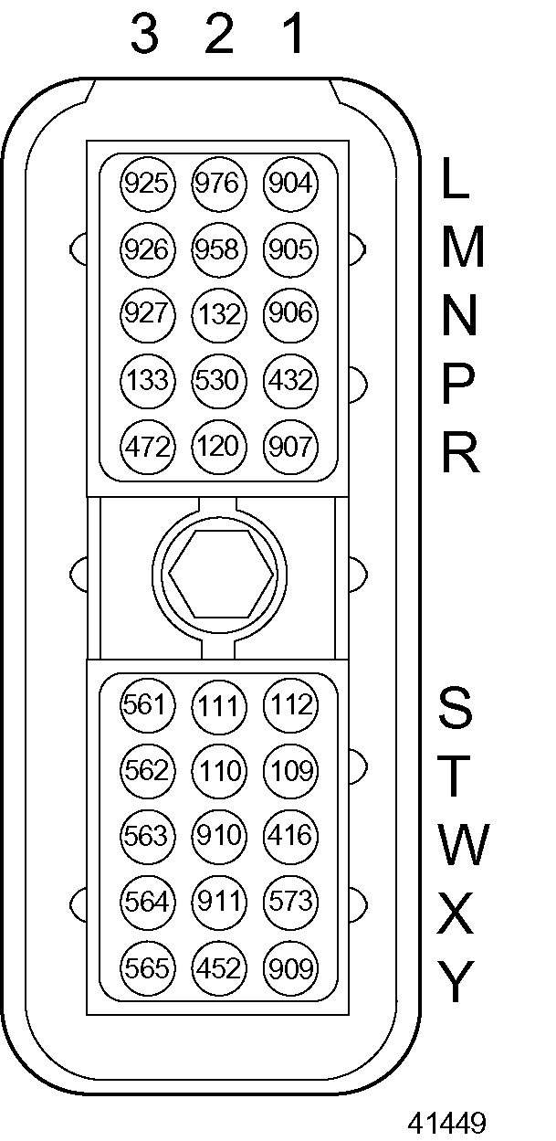
Figure 2. Engine Sensor Harness 30–pin Connector
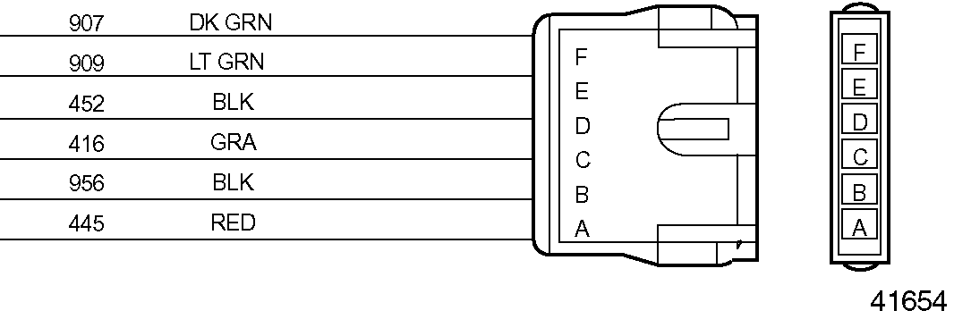
Figure 3. Throttle Actuator Connector
- If code is still active, go to step .
- If the code is no longer active, refer to "6.15.2 Verification" .
- Unplug the Electronic Foot Pedal Assembly (EFPA) connector. See Figure
"Typical Electronic Foot Pedal Assembly Device (Shown with TPS 6–pin Connector)"
. Using a digital voltmeter, insert the positive (+) lead into pin C (wire 916, red and black) and the negative (-) lead into pin A (wire 952, black) of the TPS 6–pin connector (see Figure
"Typical Electronic Foot Pedal Assembly Connector (Shown for TPS 6–pin Connection)"
).
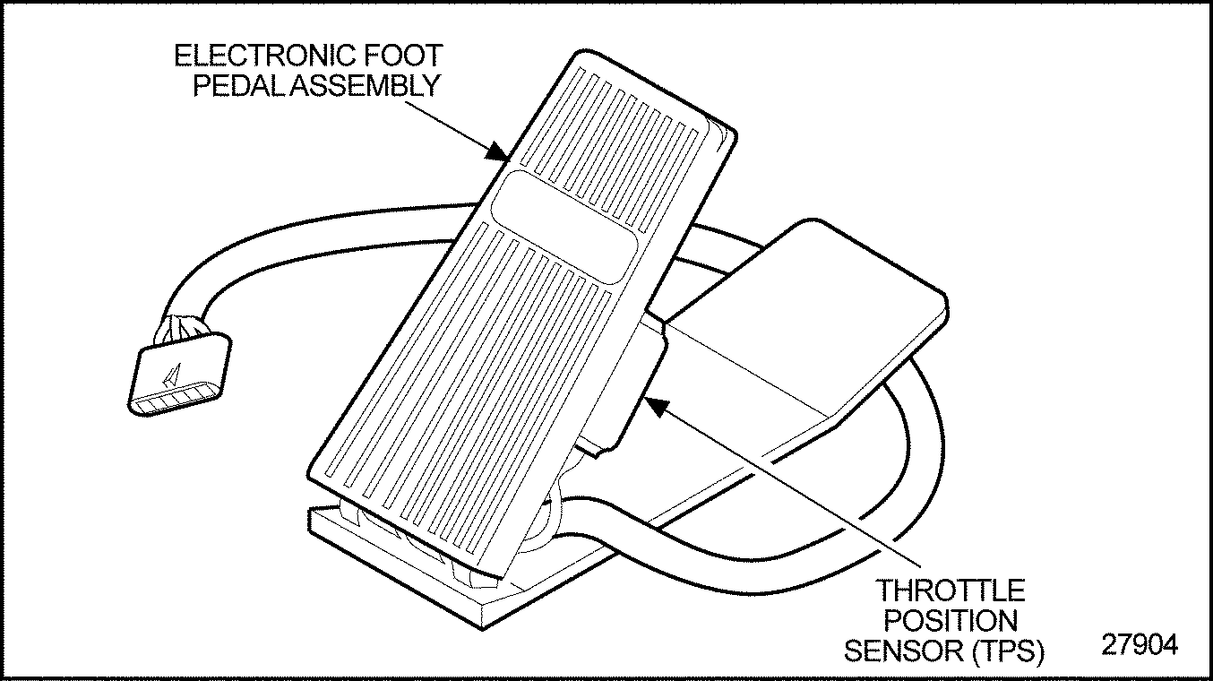
Figure 4. Typical Electronic Foot Pedal Assembly Device (Shown with TPS 6–pin Connector)

Figure 5. Typical Electronic Foot Pedal Assembly Connector (Shown for TPS 6–pin Connection)
- Turn the ignition on and monitor the voltage at the EFPA connector (see Figure
"Typical Electronic Foot Pedal Assembly Connector (Shown for TPS 6–pin Connection)"
).
- If the voltage is less than 4.9 V, then go to step .
- If the voltage is between 4.9 to 5.1 V recheck the 51 kΩ resistor. Go to step .
- If the code is no longer active, refer to "6.15.2 Verification" .
- Verify the proper operation of the Manifold Absolute Pressure (MAP) sensor. Unplug the MAP sensor (see Figure
"Manifold Absolute Pressure Sensor Location — Series 60G"
). Turn the ignition on and monitor the voltage at the EFPA connector.
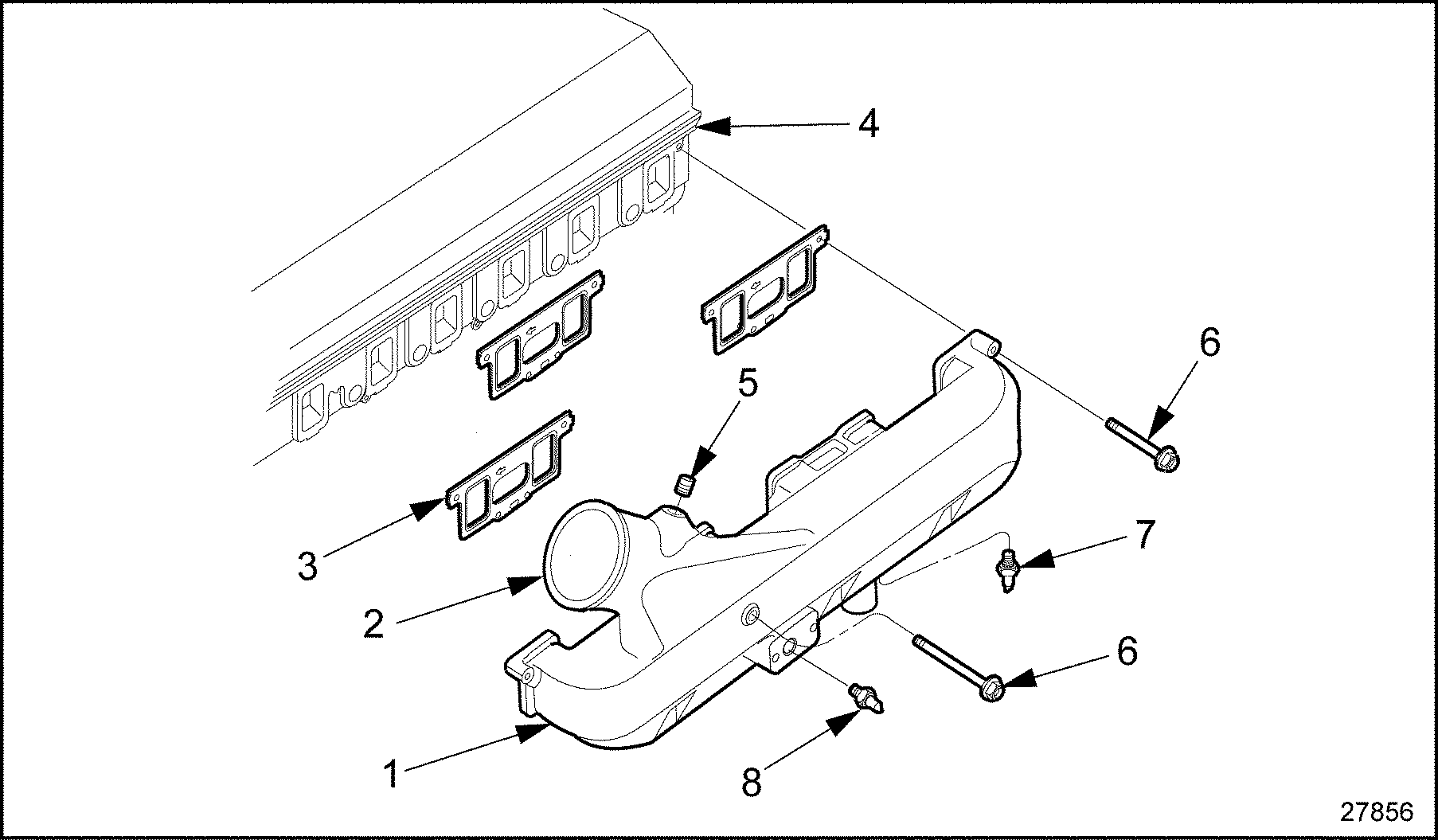
1. Intake Manifold
5. Bolt
2. Intake Manifold Inlet
6. Bolt
3. Intake Manifold Gasket
7. ATS (Low Pressure System only)
4. Cylinder Head
8. Manifold Absolute Pressure Sensor
Figure 6. Manifold Absolute Pressure Sensor Location — Series 60G
- If the voltage is between 4.9 to 5.1 V, then check the MAP sensor connector for damage and repair as required. If there is no damage to the connector, then replace the MAP sensor. Refer to "5.20.1.2 Turbocharger Wastegate Setting" .
- If the voltage is less than 4.9 V, then go to step .
- If the code is no longer active, reconnect all connectors and refer to "6.15.2 Verification" .
- Verify the proper operation of the Oil Pressure Sensor (OPS). Unplug the OPS (see Figure
"Location of Oil Pressure and Temperature Sensors"
). Turn the ignition on and monitor the voltage at the EFPA connector.

Figure 7. Location of Oil Pressure and Temperature Sensors
- If the voltage is between 4.9 to 5.1 V, then check the OPS connector for damage and repair as required. If there is no damage to the connector, then replace the OPS. Refer to "5.14.1.1 Replacing the Oil Pressure Sensor" .
- If the voltage is less than 4.9 V, then go to step .
- If the code is no longer active, reconnect all connectors and refer to "6.15.2 Verification" .
- Verify the proper operation of the Fuel Pressure Sensor (FPS). Unplug the FPS (see Figure
"Fuel Pressure Sensor Location"
). Turn the ignition on and monitor the voltage at the EFPA connector.

Figure 8. Fuel Pressure Sensor Location
- If the voltage is between 4.9 to 5.1 V, then check the FPS connector for damage and repair as required. If there is no damage to the connector, then replace the FPS.Refer to "5.10.1.1 Replacing the Fuel Pressure Sensor" .
- If the voltage is less than 4.9 V, then go to step .
- If the code is no longer active, reconnect all connectors and refer to "6.15.2 Verification" .
- Verify the proper operation of the Barometric Pressure Sensor (BARO sensor). Unplug the BARO sensor (see Figure
"Barometric Pressure Sensor and Oxygen Sensor Interface Module Location"
). Turn the ignition on and monitor the voltage at the EFPA connector.
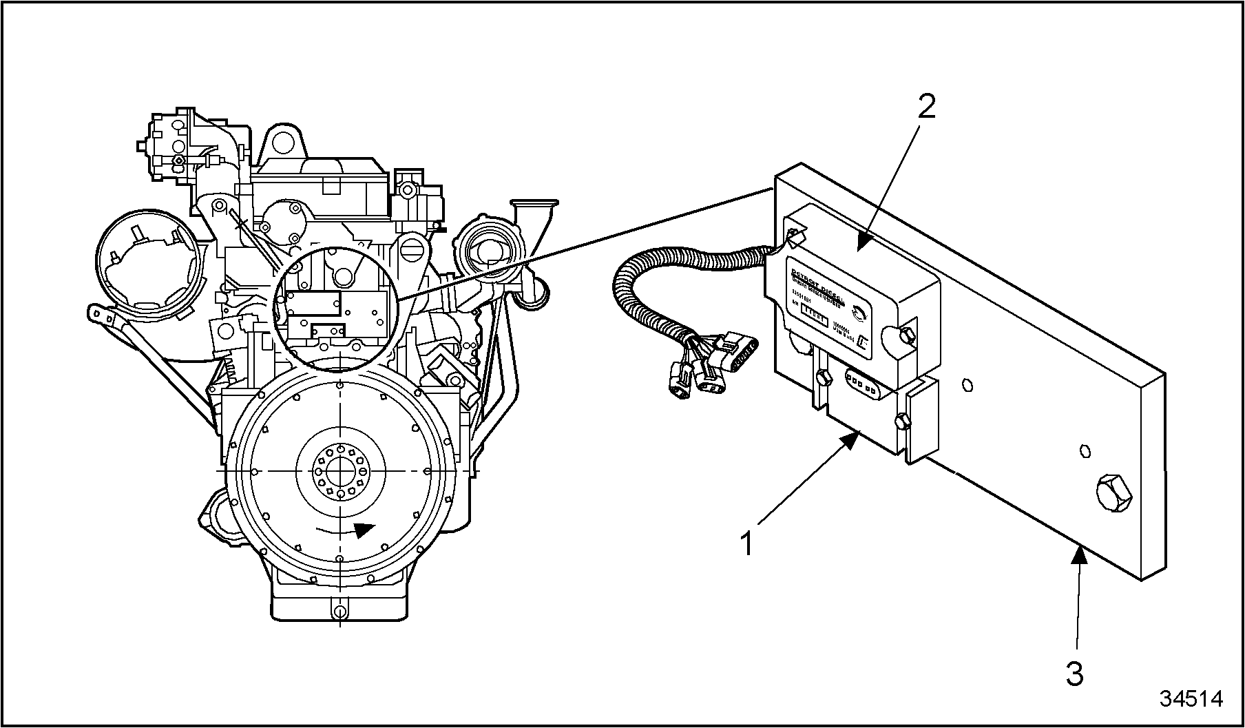
1. Barometric Pressure Sensor
3. Sensor Bracket
2. Oxygen Sensor Interface Module
Figure 9. Barometric Pressure Sensor and Oxygen Sensor Interface Module Location
- If the voltage is between 4.9 to 5.1 V, then check the BARO sensor connector for damage and repair as required. If there is no damage to the connector, then replace the BARO sensor.
- If the voltage is less than 4.9 V, then go to step .
- If the code is no longer active, reconnect all connectors and refer to "6.15.2 Verification" .
- Verify the proper operation of the oxygen sensor interface module. Unplug the oxygen sensor interface module (see Figure
"Barometric Pressure Sensor and Oxygen Sensor Interface Module Location"
). Turn the ignition on and monitor the voltage at the EFPA connector.
- If the voltage is between 4.9 to 5.1 V, then check the oxygen sensor interface module connector for damage and repair as required. If there is no damage to the connector, then replace the oxygen sensor interface module.
- If the voltage is less than 4.9 V, then go to step .
- If the code is no longer active, reconnect all connectors and refer to "6.15.2 Verification" .
- Verify the proper operation of the throttle actuator. Unplug the oxygen sensor interface module (see Figure
"Throttle Actuator for the Series 60G Engine"
). Turn the ignition on and monitor the voltage at the EFPA connector.

Figure 10. Throttle Actuator for the Series 60G Engine
- If the voltage is between 4.9 to 5.1 V, then check the throttle actuator connector for damage and repair as required. If there is no damage to the connector, then replace the throttle actuator. Refer to "5.7.3.1 Removal of Throttle Actuator" and refer to "5.7.3.2 Installation of Throttle Actuator" .
- If the voltage is less than 4.9 V, then go to step .
- If the code is no longer active, reconnect all connectors and refer to "6.15.2 Verification" .
- Check wire 416 (gray, 5 VDC sensor supply) for a short to ground at cavity W-1 in the Engine Sensor Harness (ESH) 30–pin connector (see Figure
"Engine Sensor Harness 30–pin Connector"
). If there is a short, repair or replace the wire, pins, and sockets.

Figure 11. Engine Sensor Harness 30–pin Connector
- If code is still active, go to step .
- If the code is no longer active, refer to "6.15.2 Verification" .
- Check wire 916 (red and black, 5 VDC sensor supply) for a short to ground at cavity A-3) in the Vehicle Interface Harness (VIH) 30–pin connector (see Figure
"Vehicle Interface Harness 30–pin Connector"
). If there is a short, repair or replace the wire, pins, and sockets.

Figure 12. Vehicle Interface Harness 30–pin Connector
- If code is still active, call Detroit Diesel Technical Service.
- If the code is no longer active, refer to "6.15.2 Verification" .
Section 6.15.2
Verification
Verify that troubleshooting was successful:
- Check the DDR to see if SID 232, FMI 1, Flash Code 46 is still active.
- If the code is still active, go to step 2.
- If the code is not active, troubleshooting is complete.
- If code is still active, call Detroit Diesel Technical Service.
| Series 50G and 60G Troubleshooting Guide - 6SE482 |
| Generated on 10-13-2008 |