Section 2.2
DDEC System--How It Works
The major components of the DDEC system consist of the Electronic Control Module (ECM), the Electronic Unit Injectors (EUI) and the various system sensors. The purpose of the sensors is to provide information to the ECM regarding various engine performance characteristics. The information sent to the ECM is used to instantaneously regulate engine and vehicle performance.
Section 2.2.1
Electronic Unit Injector
An electronic unit injector incorporates a solenoid operated poppet valve which performs the injection timing and metering functions. When the solenoid valve is closed, pressurization and fuel injection is initiated. Opening the solenoid valve releases injection pressure, ending injection. The duration of valve closure determines the quantity of fuel injected. See Figure "Electronic Unit Injector" .

Figure 1. Electronic Unit Injector
Section 2.2.2
Electrical Connectors
Provide water-tight connections for the harnesses between the sensors and the ECM.
Section 2.2.3
Air Temperature Sensor
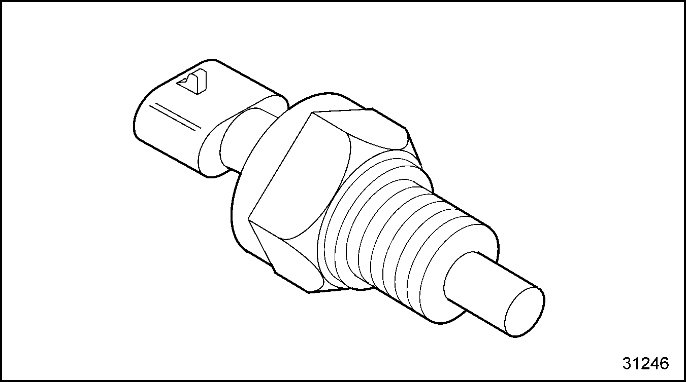
The air temperature sensor is located in the air intake manifold and monitors the air temperature entering the engine. The ECM adjusts the engine timing to reduce white smoke, improve cold starts, and provide engine protection. See Figure "Air Temperature Sensor" . For EGR sensor, see Figure "Air Temperature Sensor With EGR" .

Figure 2. Air Temperature Sensor

Figure 3. Air Temperature Sensor With EGR
Section 2.2.4
Coolant Temperature Sensor (CTS)
The CTS is located on the right side of the engine. The engine protection feature will be triggered if the coolant temperature exceeds the specified limits. See Figure "Coolant Temperature Sensor" . See Figure "Coolant Temperature Sensor With EGR" for sensor with EGR.

Figure 4. Coolant Temperature Sensor

Figure 5. Coolant Temperature Sensor With EGR
Section 2.2.5
Fire Truck Pump Pressure Sensor
The fire truck pump pressure sensor is used to monitor water pressure for the Pressure Governor System in the DDEC system. The signal back to the ECM changes r/min which allows the fire truck water pump to maintain a steady water pressure during pumping operation in fire trucks. See Figure "Fire Truck Pump Pressure Sensor" .

Figure 6. Fire Truck Pump Pressure Sensor
Section 2.2.6
The Synchronous Reference Sensor (SRS) and Timing Reference Sensor (TRS)
These sensors control the timing of the engine. The SRS sensor provides a "once per cam revolution" signal and the TRS sensor provides a "36 per crankshaft revolution" signal. Working together, these sensors tell the ECM which cylinder is at top-dead-center for cylinder firing. Precise monitoring of piston position allows for optimum injection timing, resulting in excellent fuel economy and performance with low emissions. See Figure "Timing Reference Sensor and Synchronous Reference Sensor" for the SRS and the TRS.

Figure 7. Timing Reference Sensor and Synchronous Reference Sensor
Section 2.2.7
Oil and Fuel Temperature Sensors
The oil temperature sensor optimizes idle speed and injection timing to improve cold starting ability and reduce white smoke. This sensor will activate the engine protection system if the oil temperature is higher than normal.
The fuel temperature sensor provides a signal to the ECM. The ECM utilizes the fuel temperature signal to adjust the fueling for changes in the fuel density as a function of temperature to maintain horsepower. See Figure "Oil and Fuel Temperature Sensors" . For sensors with EGR, see Figure "Oil and Fuel Temperature Sensors With EGR" .

Figure 8. Oil and Fuel Temperature Sensors

Figure 9. Oil and Fuel Temperature Sensors With EGR
Section 2.2.8
Electronic Control Module
The ECM is the brain of the computer system, receiving electronic inputs from the operator as well as from the engine and vehicle mounted sensors. See Figure "Electronic Control Module" .

Figure 10. Electronic Control Module
Section 2.2.9
Coolant Level Sensor (CLS)
The engine protection feature will be triggered if the coolant level sensor detects a low coolant level. See Figure "Coolant Level Sensor" .

Figure 11. Coolant Level Sensor
Section 2.2.10
Throttle Position Sensor (TPS)
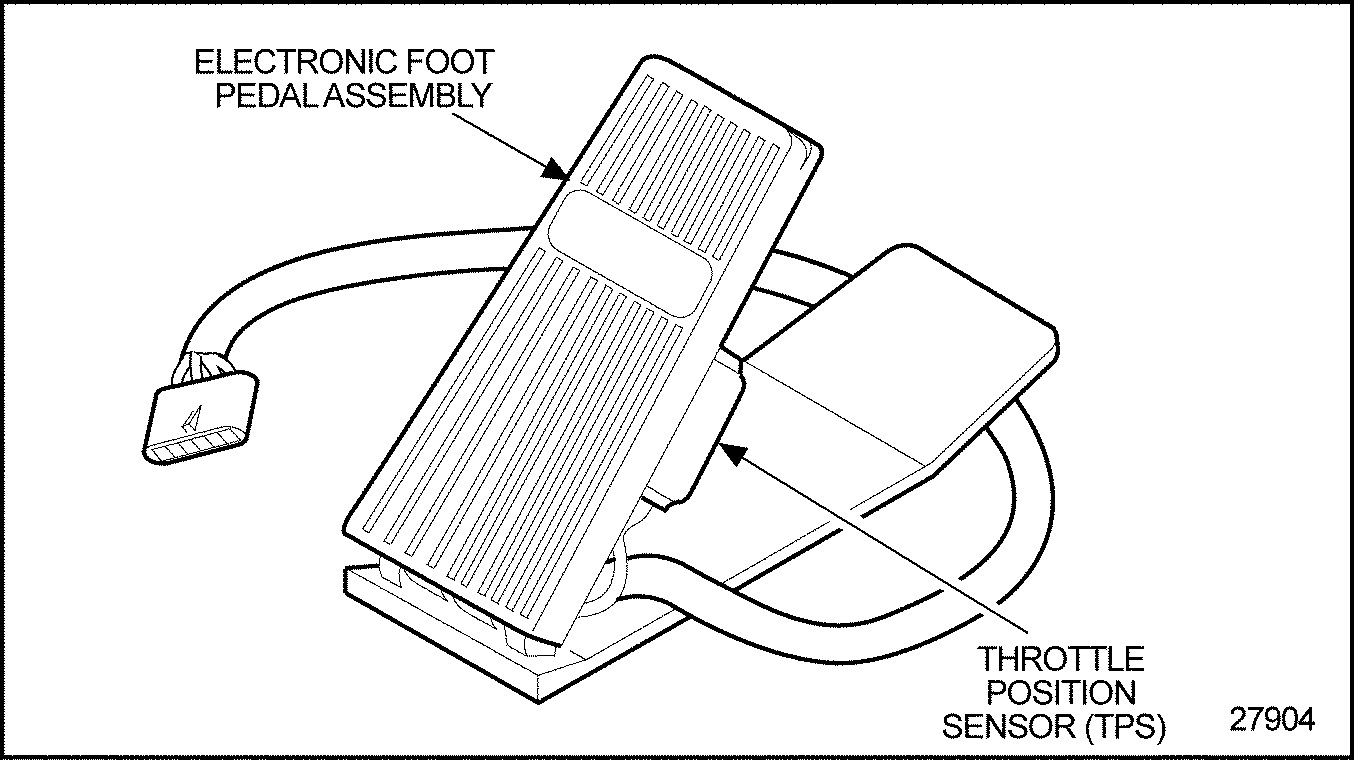
The electronic foot pedal assembly instantaneously converts the operator's throttle input into a signal to the ECM. The throttle response is fast and accurate. The TPS is self-calibrated, and requires no maintenance. See Figure "Throttle Position Sensor" .

Figure 12. Throttle Position Sensor
Section 2.2.11
Vehicle Speed Sensor (VSS)
The VSS provides the ECM with the vehicle road speed for use with cruise control, vehicle speed limiting, and progressive shifting. See Figure "Vehicle Speed Sensor" .

Figure 13. Vehicle Speed Sensor
Section 2.2.12
Turbocharger Boost Sensor (TBS)
In monitoring turbocharger compressor discharge, the TBS provides air pressure data to the ECM for smoke control during engine acceleration. See Figure "Turbocharger Boost Sensor" . For sensor with EGR, see Figure "Turbocharger Boost Sensor With EGR" .

Figure 14. Turbocharger Boost Sensor

Figure 15. Turbocharger Boost Sensor With EGR
Section 2.2.13
Oil Pressure Sensor (OPS)
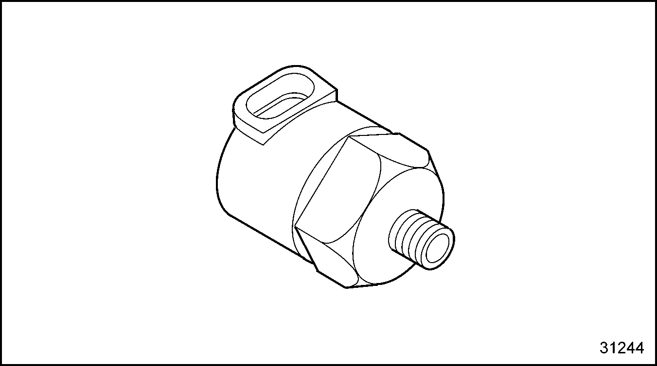
The OPS will activate the engine protection system when the oil pressure falls below a normal oil pressure at a given engine r/min. See Figure "Oil Pressure Sensor" . For sensor with EGR, see Figure "Oil Pressure Sensor With EGR" .

Figure 16. Oil Pressure Sensor

Figure 17. Oil Pressure Sensor With EGR
Section 2.2.14
Fuel Pressure Sensor (FPS)
The FPS monitors fuel pressure to warn the operator of impending power loss. This feature is optional. It is not used in international applications. See Figure "Fuel Pressure Sensor" .

Figure 18. Fuel Pressure Sensor
Section 2.2.15
Turbo Compressor Outlet (TCO) Temperature Sensor
The TCO sensor is located in the outlet of the turbocharger, compressor side, and measures temperature. If the temperature gets too high, the ECM can derate the power. See Figure "Turbo Compressor Outlet Temperature Sensor" .

Figure 19. Turbo Compressor Outlet Temperature Sensor
Section 2.2.16
Turbocharger Speed Sensor
The turbocharger speed sensor is located in the center section of the turbocharger, and sends speed signals to the ECM. See Figure "Turbocharger Speed Sensor" .

Figure 20. Turbocharger Speed Sensor
Section 2.2.17
Air Filter Restriction Sensor (AFRS)
The AFRS is part of the Maintenance Alert System (MAS) and is used to monitor air inlet restriction. See Figure "Air Filter Restriction Sensor" .

Figure 21. Air Filter Restriction Sensor
Section 2.2.18
Exhaust Temperature Sensor
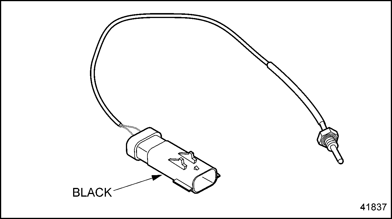
This sensor is OEM/Customer installed in the exhaust and is used to prevent engine/converter damage. See Figure "Exhaust Temperature Sensor" .

Figure 22. Exhaust Temperature Sensor
Section 2.2.19
Relative Humidity (RHS) / Turbo Compressor Inlet (TCI) Temperature Sensor
The RHS/TCI sensor is located by the OEM in the piping between the air filter and turbo inlet. See Figure "Relative Humidity / Turbo Compressor Inlet (TCI) Temperature Sensor " .

Figure 23. Relative Humidity / Turbo Compressor Inlet (TCI) Temperature Sensor
Section 2.2.20
Barometric Pressure Sensor
This sensor is located in the engine harness, tie-wrapped on the right side under the manifold. See Figure "Barometric Pressure Sensor" .

Figure 24. Barometric Pressure Sensor
Section 2.2.21
EGR Delta Pressure Sensor (DPS)
The EGR Delta-P sensor measures the difference in pressure across the venturi in the cold pipe. It is used with the EGR temperature sensor to determine exhaust gas flow. See Figure "EGR Delta Pressure Sensor " .

Figure 25. EGR Delta Pressure Sensor
Section 2.2.22
EGR Temperature Sensor
The EGR temperature sensor is located in the cold side EGR piping and monitors temperature. This sensor and the Delta-P sensor data are used to calculate the exhaust gas flow. See Figure "EGR Temperature Sensor" .

Figure 26. EGR Temperature Sensor
Section 2.2.23
Oil Level Sensor (OLS)
The OLS is part of the Maintenance Alert System (MAS) and monitors the oil level. See Figure "Oil Level Sensor" .

Figure 27. Oil Level Sensor
| DDEC III/IV Single ECM Troubleshooting Guide - 6SE497 |
| Generated on 10-13-2008 |