Section 3.3
Piston Oil Spray Nozzle(S)
Perform the following procedures for removal and installation of the piston oil spray nozzle.
Section 3.3.1
Piston Oil Spray Nozzle(s) Removal
Remove the piston oil spray nozzle(s) as follows:
Note: These procedures refer to bolt-on piston oil spray nozzles only.
- Remove the oil pan. Refer to "3.2.1 Oil Pan Removal" .
- Remove the inspection cover on the flywheel housing and install the engine cranking tool (J–46392)
. See Figure
"Installing the Engine Cranking Tool"
. Rotate the crankshaft to gain access to the nozzle(s).
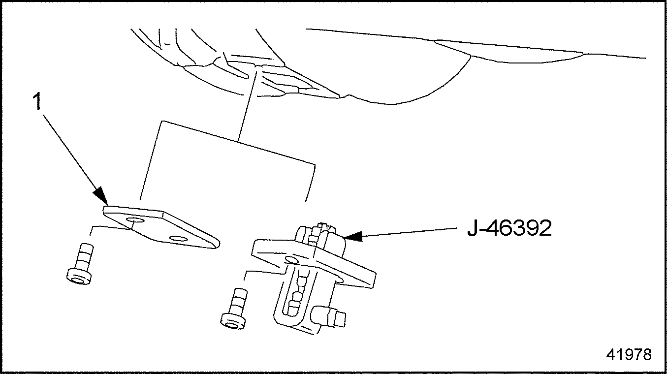
1. Inspection Cover
Figure 1. Installing the Engine Cranking Tool
- Remove the hollow-core bolt that attaches each piston oil spray nozzle to the underside of the cylinder block. Remove the oil spray nozzle from the engine. See Figure
"Removing the Piston Oil Spray Nozzle(s)"
.

1. Piston Spray Nozzle
2. Hollow Core Bolt
Figure 2. Removing the Piston Oil Spray Nozzle(s)
Note: Piston cooling nozzle tool J–47301 is used to check the proper alignment of the piston oil spray nozzles for non-EGR and EGR engines built before March 2005. EGR engines built starting March 2005 do not use this tool. For identification of the oil spray nozzles see Figure "Piston Cooling Nozzles" .

Figure 3. Piston Cooling Nozzles
- For non-EGR and EGR engine built before March 2005, check the piston oil spray nozzle(s) using the piston cooling jet tool (J–47301)
. See Figure
"Checking the Piston Oil Spray Nozzle(s)"
.

1. Knurled Bolt
3. Setting Rod
2. Piston Oil Spray Nozzle
4. Setting Device
Figure 4. Checking the Piston Oil Spray Nozzle(s)
- Secure the setting device (part of toolset J–47301) in a vise with protective jaws.
- Remove the knurled bolt and setting rod from the setting device. Install the piston oil spray nozzle on the setting device. Hand tighten the knurled bolt enough to hold the nozzle firmly.
- Insert the correct end of the setting rod through the base of the setting device and into the tip of the piston oil spray nozzle. If the setting rod will not insert into the tip of the piston oil cooling nozzle, discard the nozzle and replace with a new nozzle.
Note: The setting rod is double ended, one end has a diameter of 2.6 mm (0.102 in.) for non-EGR engines and the other end is 3.0 mm (0.118 in.) for EGR engines.
Section 3.3.2
Piston Oil Spray Nozzle(s) Installation
Install the piston oil spray nozzle(s) as follows:
- Install each piston oil spray nozzle in the block with the locator pin correctly installed. See Figure
"Installing the Piston Oil Spray Nozzle(s)"
. Tighten the hollow-core bolt to 40 N·m (30 lb·ft).

1. Pin Seat
2. Locator Pin
Figure 5. Installing the Piston Oil Spray Nozzle(s)
Note: The locator pin on the base of the piston oil spray nozzle must be inserted into the pin seat in the cylinder block until it engages.
NOTICE:
For EGR engines built March 2005 and later, the piston oil spray nozzle must be aligned to the center of the oil lubricating hole in the bottom of the piston. If the nozzle is not properly aligned, inadequate lubrication to the piston will result in the failure of the engine.
- For EGR engines built March 2005 and later check to ensure that the piston oil spray nozzle(s) are aligned with the oil hole in the base of the piston as follows:
- Bar the engine until the piston is at bottom dead center and check that the alignment of the oil spray nozzle tip is in the center of the piston oil lubricating hole. The nozzle should be inside the piston oil hole and centered.
- If the oil spray nozzle does not align in the center of the piston oil lubricating hole or is not inside the oil hole in the piston, replace the nozzle. Do not bend the nozzles to align.
- Install the oil pan. Refer to "3.2.2 Oil Pan Installation" .
- Remove the engine cranking tool (J–46392)
and install the the inspection cover. Torque bolts on cover to 25 N·m (18 lb·ft)See Figure
"Installing the Engine Cranking Tool"
.
1. Inspection Cover
Figure 6. Installing the Engine Cranking Tool
- Fill the crankcase to the specified oil level listed in Table "Lubricating Oil Capacity" . Do not overfill the crankcase.
| MBE 4000 Service Manual - 6SE412 |
| Generated on 10-13-2008 |