Section 4.2
Coolant Pump
Perform the following procedures for removal and installation of the coolant pump.
Section 4.2.1
Coolant Pump Removal
Remove the coolant pump as follows:
|
HOT COOLANT |
|
To avoid scalding from the expulsion of hot coolant, never remove the cooling system pressure cap while the engine is at operating temperature. Wear adequate protective clothing (face shield, rubber gloves, apron, and boots). Remove the cap slowly to relieve pressure. |
- Drain the coolant from the engine. Refer to "4.1.1 Cooling System Draining and Flushing" .
- Remove the fan.
- Release the tension on the main drive belt and the fan belt and set the belts aside
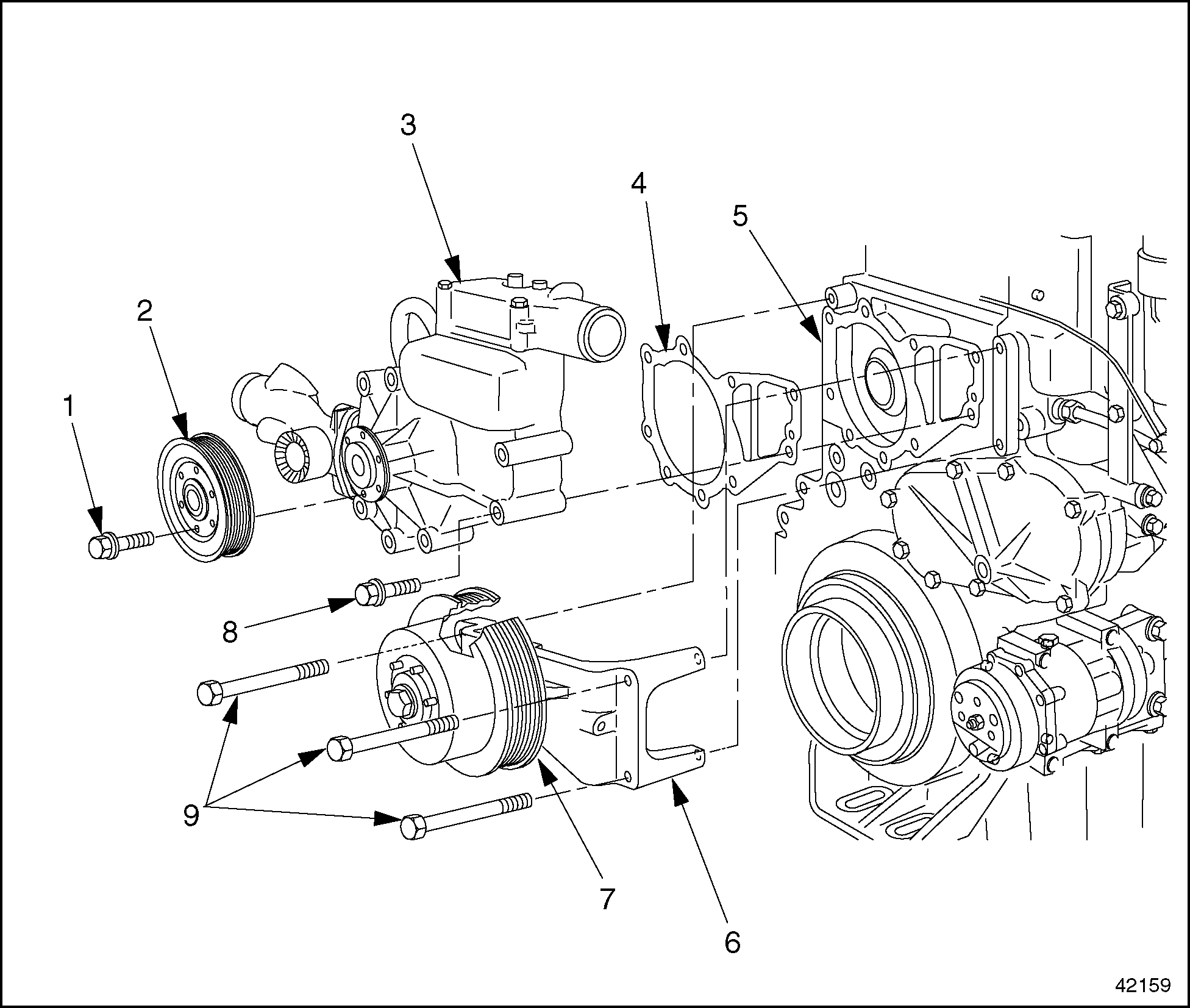
- Remove the fan support from the cylinder block. See Figure
"Fan Support and Coolant Pump Removal"
. Refer to "4.7.1 Coolant Temperature Sensor Disassembly"
.

1. Coolant Pump Pulley Mounting Bolt
6. Fan Support
2. Coolant Pump Pulley
7. Fan Pulley
3. Coolant Pump Assembly
8. Pump Mounting Bolt
4. Gasket
9. Fan Support Mounting Bolt
5. Cylinder Block
Figure 1. Fan Support and Coolant Pump Removal
- Remove the coolant pump pulley from the coolant pump housing.
- Remove the mounting bolts from the front idler and tensioner support. Slide the support to the right-hand side of the engine. See Figure "Coolant Pump Inlet Pipe (exploded view)" .
- Remove the upper alternator mounting bolt, loosening the alternator enough to tilt it out of the way.
- Remove the inlet pipe from the coolant pump housing. See Figure
"Coolant Pump Inlet Pipe (exploded view)"
.

1. Lower Coolant Tube
5. Coolant Pump Housing
2. Inlet Pipe Mounting Bolt
6. Front Idler and Tensioner Support
3. Inlet Pipe
7. Coolant Pump Support Mounting Bolt
4. Inlet Pipe Gasket
8. Upper Coolant Tube
Figure 2. Coolant Pump Inlet Pipe (exploded view)
Note: Catch any coolant that runs out of the inlet pipe or coolant pump in a suitable container.
- Remove the upper coolant tube from the thermostat housing.
- Remove the coolant pump from the cylinder block. Discard the gasket.
- On both the coolant pump and the cylinder block, clean the sealing surfaces (where the gasket was attached) of any adhering bits of gasket material.
- Remove the thermostat housing from the coolant pump.
Section 4.2.2
Coolant Pump Disassembly
Disassemble the coolant pump unit as follows:
- Remove the coolant pump from the engine. Refer to "4.2.1 Coolant Pump Removal" .
- Using a puller, pull the coolant pump hub away from the bearing. See Figure
"Pulling the Hub"
.

1. Puller
3. Coolant Pump Housing
2. Hub
Figure 3. Pulling the Hub
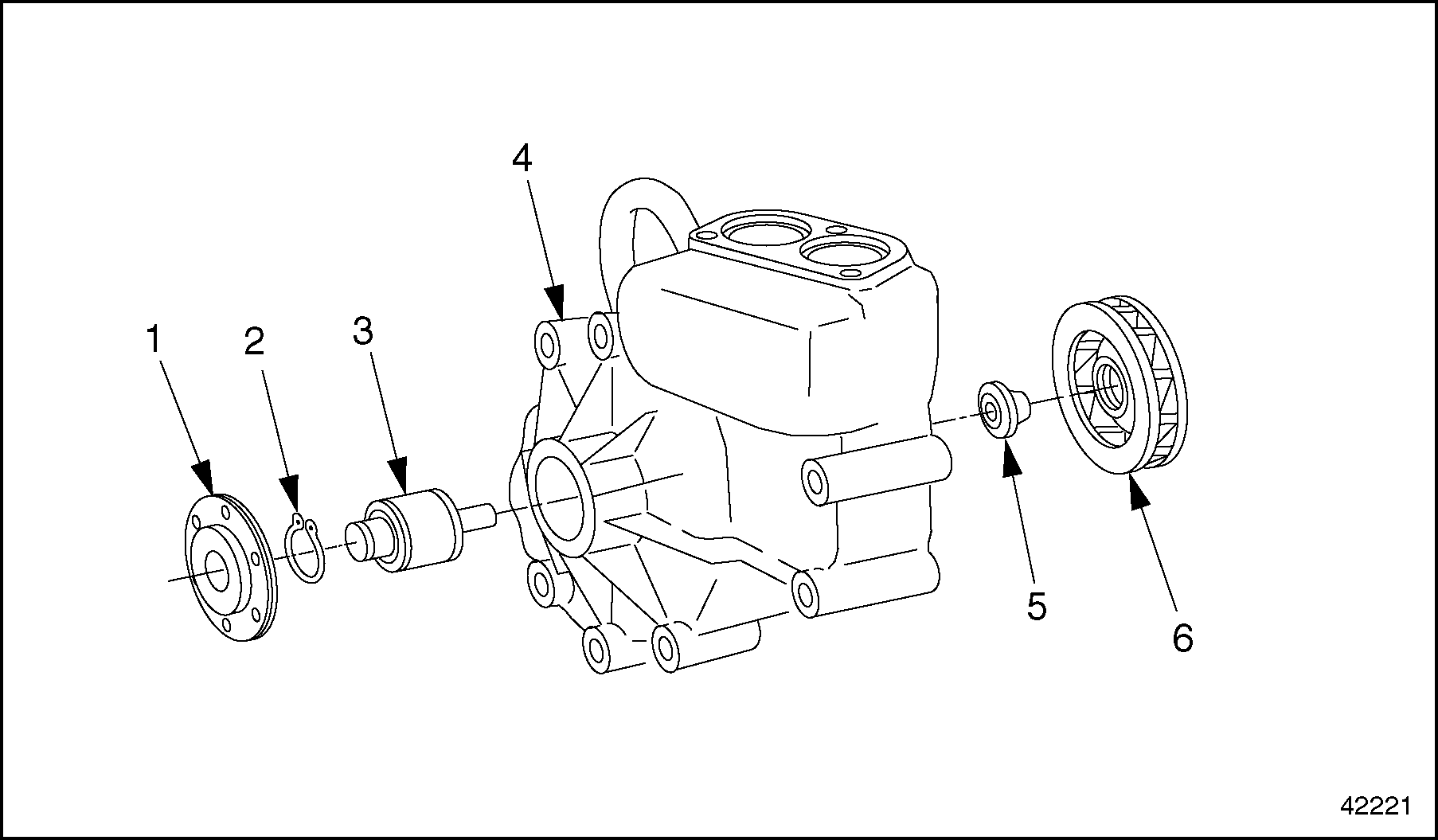
- Remove the snap ring from the coolant pump housing. See Figure
"Coolant Pump Assembly (exploded view)"
.

1. Hub
4. Coolant Pump Housing
2. Snap Ring
5. Sleeve Seal
3. Drive Shaft and Bearing Assembly
6. Impeller
Figure 4. Coolant Pump Assembly (exploded view)
- Using an appropriate drift, press the drive shaft and bearing assembly out of the impeller and through the coolant pump housing. This frees the impeller from the housing. See Figure
"Removing the Drive Shaft"
.

1. Sleeve Seal
4. Receptacle
2. Drift
5. Drive Shaft and Bearing Assembly
3. Impeller
Figure 5. Removing the Drive Shaft
- Remove the sleeve seal from the coolant pump housing.
Section 4.2.2.1
Coolant Pump Inspection
Inspect the coolant pump unit as follows:
- Check all coolant pump components for signs of damage. Replace any damaged components.
- Measure the following wear dimensions. Replace any component that is not within tolerance as Listed in Table
"Coolant Pump Assembly Wear Dimensions"
.
Description
Wear Dimensions, mm (in.)
Drive Shaft Diameter (at the hub)
25.048-25.061 (0.9861-0.9867)
Hub Inside Diameter
24.995-25.008 (0.9841-0.9846)
Bearing Outside Diameter
54.981-54.994 (2.1646-2.1651)
Bearing Housing Diameter
54.930-54.960 (2.1626-2.1638)
Drive Shaft Diameter (at the impeller)
15.045-15.056 (0.5923-0.5928)
Impeller Inside Diameter
15.000-15.018 (0.5906-0.5913)
Impeller Outside Diameter
124-125 (4.88-4.92)
Impeller - Maximum Out-Of-Round
0.15 (0.0059)
Table 7. Coolant Pump Assembly Wear Dimensions
Section 4.2.3
Coolant Pump Assembly
Assemble the coolant pump unit as follows:
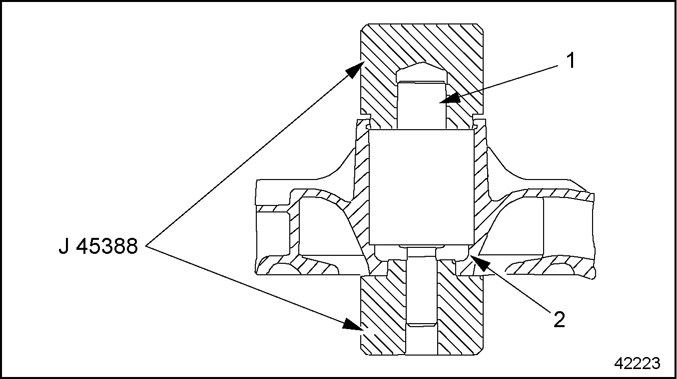
- Press the drive shaft and bearing assembly into the coolant pump housing. See Figure
"Installing the Drive Shaft"
.

1. Drive Shaft
2. Coolant Pump Housing
Figure 6. Installing the Drive Shaft
- Place the coolant pump housing in a press.
- Place the coolant pump pressure piece, (J 45388 ) , over the outer bearing race.
- Place the receptacle, (J 45388 ) , under the coolant pump housing.
- Press the outer race of the bearing into the coolant pump housing.
NOTICE:
To prevent damage to the drive shaft and bearing assembly, press only on the outer bearing race.
- Secure the bearing in place with the snap ring.

PERSONAL INJURY
To avoid injury from hot surfaces, wear protective gloves, or allow engine to cool before removing any component.
- Press the hub onto the drive shaft and bearing assembly.
- Heat the hub to 175°F (80°C).
NOTICE:
To prevent damage to the bearing, make sure the drive shaft is supported evenly before pressing on the hub.
- Press the hub onto the drive shaft, while holding the bearing and drive shaft assembly to prevent it from turning. Make sure the hub is flush with the end of the drive shaft.
- Heat the hub to 175°F (80°C).
- Using the coolant pump bearing drift (352 589 08 15 00)
, press the sleeve seal into the coolant pump housing. See Figure
"Installing the Sleeve Seal"
.

1. Sleeve Seal
3. Coolant Pump Housing
2. Drive Shaft
Figure 7. Installing the Sleeve Seal
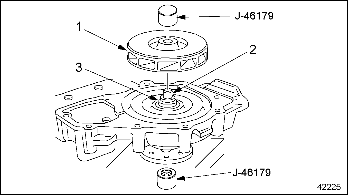
- Press the impeller onto the drive shaft and bearing assembly. See Figure
"Pressing in the Impeller"
.

1. Impeller
3. Sleeve Seal
2. Drive Shaft
Figure 8. Pressing in the Impeller
Note: Secure both the drive shaft and hub to prevent them from turning while the impeller is being installed.
- Measure the gap between the impeller and the coolant pump housing. This gap, listed in Table
"Coolant Pump Assembly, Critical Dimension"
, must be more than 0.6 mm (0.023 in.) and less than 1.0 mm (0.039 in.). See Figure
"Gap Between the Impeller and the Housing"
.
Description
mm (in.)
Gap Between the Impeller and the Coolant Pump Housing
0.6-1.0 (0.023-0.039)
Table 14. Coolant Pump Assembly, Critical Dimension
1. Impeller
2. Coolant Pump Housing
Figure 9. Gap Between the Impeller and the Housing
- Rotate the coolant pump drive shaft to make sure it moves easily and freely.
- Install the coolant pump on the engine.
Section 4.2.4
Coolant Pump Installation
Install the coolant pump as follows:
- Install the coolant pump on the cylinder block. Install a new gasket. Tighten the mounting bolts 30 N·m (22 lb·ft).
- Connect the inlet pipe to the coolant pump housing, as removed. Install a new gasket on the mating surface between the inlet pipe and the coolant pump housing. Tighten the inlet pipe mounting bolts 50 N·m (37 lb·ft).
- Tilt the alternator back into the correct position. Install the upper alternator mounting bolt and restore the alternator to operating condition.
- Install the upper coolant tube onto the thermostat housing.
- Install the coolant pump pulley and the mounting bolts attaching the coolant pump pulley to the coolant pump. Tighten the bolts 25 N·m (18 lb·ft).
- Move the front idler and tensioner support back into place on the cylinder block. Tighten the mounting bolts 60 N·m (44 lb·ft).
- Install the fan support on the cylinder block.
- Release the belt tensioners for the main drive and fan belts. Route the two belts around their pulleys and restore the belt tension.
- Install the fan.
- Fill the engine with coolant, as removed, and check for leaks.
| MBE 4000 Service Manual - 6SE412 |
| Generated on 10-13-2008 |