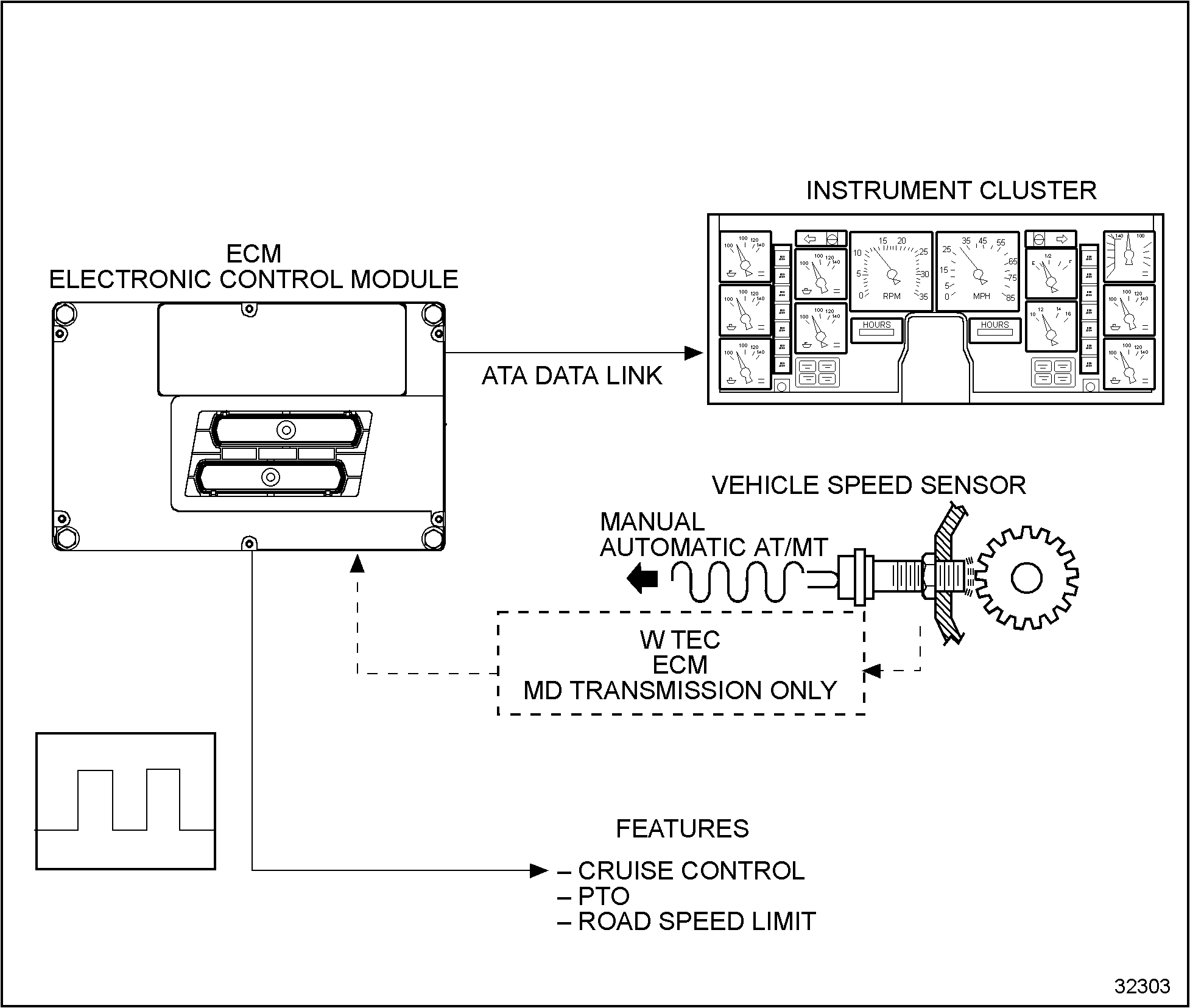
For the Vehicle Speed Sensor (VSS) function diagram, see Figure
“Vehicle Speed Sensor Function Diagram”
.

Figure 1. Vehicle Speed Sensor Function Diagram
Section 45.1.1
Signal Function
Transmission tail-shaft speed is detected by a magnetic pickup mounted on the transmission that senses the rotation of a 16–toothed gear installed on the rear of the transmission. The resultant AC (alternating current) sine wave signal is received by the ECM and is utilized along with tire size and axle ratio, to calculate vehicle speed. Calculated vehicle speed is transmitted to the instrument cluster on the ATA (American Trucking Association) data link to operate the speedometer in the instrument cluster. Calculated vehicle speed is also utilized in the control strategies that control features such as Cruise Control, PTO operation and Road Speed Limiting.
W TEC MD transmissions utilize an internal VSS sensor that sends a signal to the W TEC ECM. The W TEC ECM buffers the signal and sends a square wave signal to the engine ECM.
Section 45.1.2
Fault Detection Management
When the ECM determines that the vehicle is operating at 0 mph, the ECM performs diagnostic checking on the VSS circuitry. A voltage signal is transmitted on the VSS circuitry by the ECM and will detect if the return voltage is out of range high or low.
An out of range low code normally indicates an open, short to ground condition. An out of range high code normally indicates a short to voltage condition. When a VSS fault condition is detected, the ECM disables cruise control, PTO operation, and if road speed limiting is enabled, will limit the engine r/min in all gears.
On vehicles equipped with MD (W TEC) transmissions, no fault codes will be sent in the event of a VSS sensor circuit failure. Any VSS faults set with vehicles equipped with MD transmissions only diagnose the communication circuit between the engine ECM and the transmission ECM. Refer to the Allison W TEC Maintenance/Diagnostic Manual to diagnose any MD VSS sensor problems.
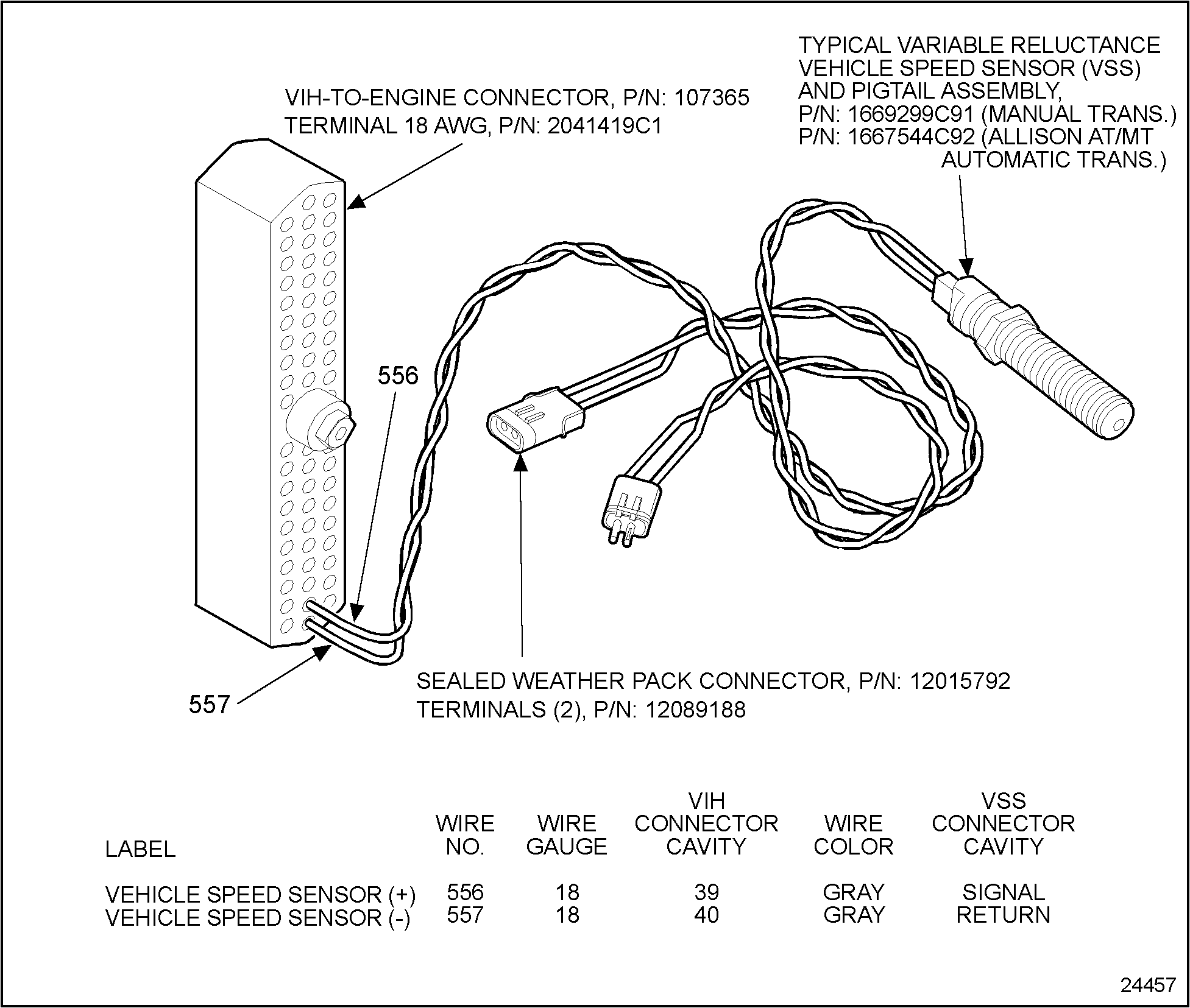
For the Vehicle Speed Sensor, see Figure
“Vehicle Speed Sensor “
.

Figure 2. Vehicle Speed Sensor
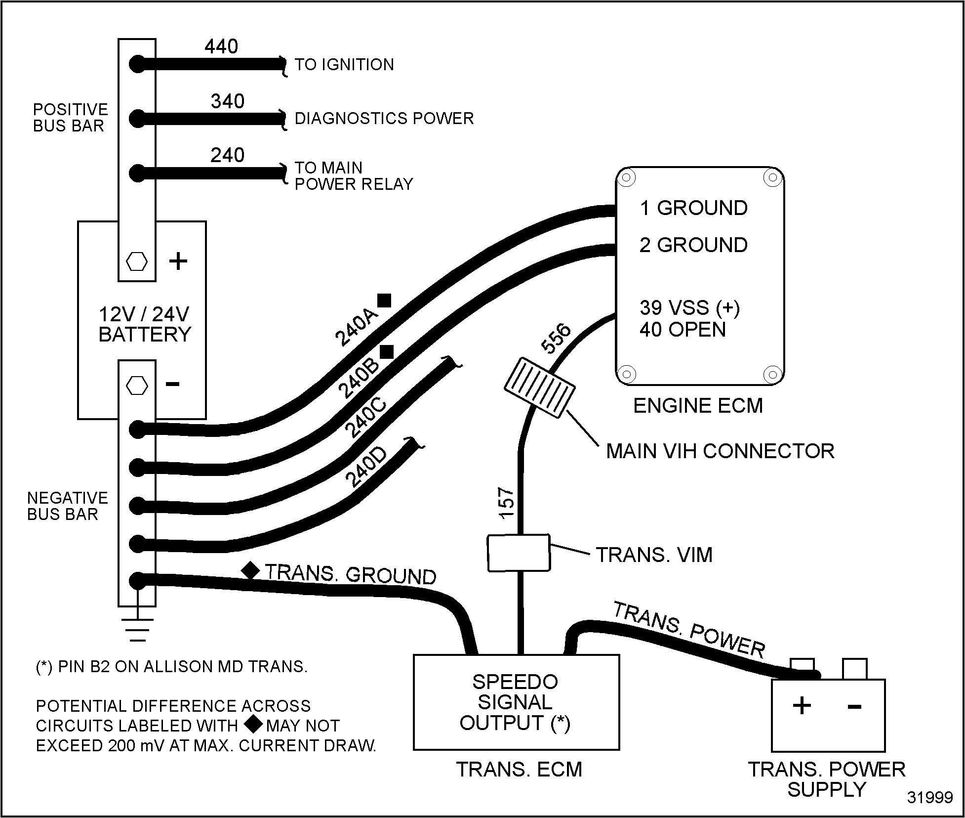
For the Vehicle Speed Sensor recommended wiring see Figure
“Recommended Wiring for a Digital Vehicle Speed Input Signal — Common Ground Architecture”
.

Figure 3. Recommended Wiring for a Digital Vehicle Speed Input Signal — Common Ground Architecture

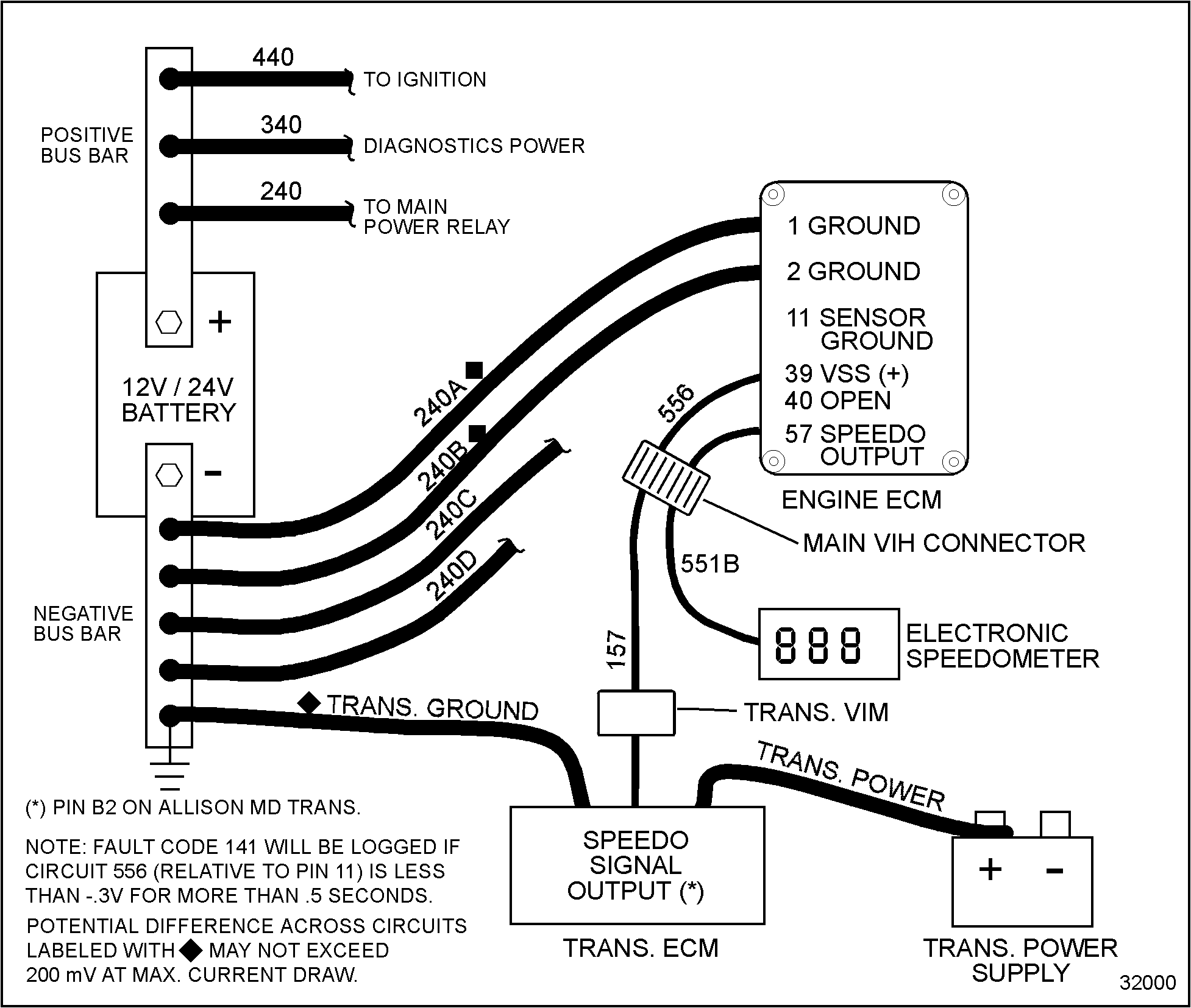
Figure 4. Recommended Wiring for a Digital Vehicle Speed Input Signal and Optional Speedometer Output
The voltage checks at the VSS connector with key ON, engine OFF, are listed in Table
“Key ON, Engine OFF — Voltage Checks at Vehicle Speed Signal Connector”
. Checks are made with the VSS sensor connector disconnected.
| +Test Points- | Spec | Comments |
| B to Grd | 2 to 3 v | ECM pull up voltage when sensor disconnected. If no voltage present check for open or shorts
|
| A to Grd | 2 to 3 v |
The VSS sensor continuity checks are listed in Table
“Vehicle Speed Signal Sensor Continuity Checks”
. Checks are made with the VSS sensor disconnected. Measure resistance through the sensor.
| +Test Points- | Spec | Comments |
| B to Grd | > 100 Ω | If less than 100 Ω, check for short to ground. |
| B to Grd | > 100 Ω | If less than 100 Ω, check for short to ground. |
| B to A | 600-800 Ω | Manual Transmission. |
| B to A | 1200-1450 Ω | Automatic transmission (mechanical) AT/MT. |
| B to A | See W TEC manual | Automatic transmission (electronic) MD. |
The harness resistance checks are listed in Table
“Harness Resistance Checks”
. Checks are made with the VSS sensor disconnected, the battery disconnected and the breakout box installed.
| +Test Points- | Spec | Comments |
| 40 to B | < 5 Ω | If greater than 5 Ω, check for open circuit. |
| 39 to A | < 5 Ω | If greater than 5 Ω, check for open circuit. |
| 40 to Grd | > 100 Ω | If less than 100 Ω, check for short to ground. |
| 39 to Grd | > 100 Ω | If less than 100 Ω, check for short to ground. |
The operational check is listed in Table
“Operational Check”
. Checks are made with the VSS sensor connected, the battery disconnected and the breakout box installed. Place the rear axles on jack stands with the front wheels blocked. Measure with the transmission in high gear and the engine at low idle.
| +Test Points- | Spec | Comments |
| 40 to 39 | > 2v AC | If less than 2v AC, check sensor adjustment or replace defective sensor. |
Note: To adjust sensor clearance, turn sensor in clockwise direction until contact is made on tail-shaft gear; then back out one full turn and tighten locknut. Ensure the sensor tip is free of metal chips prior to installation.
Fault code descriptions are listed in Table
“Fault Code Descriptions”
.
| Fault Code | Description |
| 141 | ECM detected low test voltage across VSS circuit for greater than .5 seconds. Possible open or short to ground. |
| 142 | ECM detected high test voltage across VSS circuit for greater than .5 seconds. Possible internal sensor short or short to power. |
| 215 | ECM detected a VSS frequency signal > 4365 Hz. |
Section 45.1.3
Extended Description
The Vehicle Speed Sensor (VSS) is located on the transmission and sends an AC signal to the ECM. The VSS sensor contains a permanent magnet that creates a magnetic field. The AC signal is created when the 16–tooth transmission speedometer gear rotates breaking the magnetic field created by the sensor. The ECM processes the AC signal and transmits vehicle speed data on the ATA Data Link and utilizes it for various engine and vehicle control strategies.
On a manual transmission, the VSS sensor is mounted at the rear of the transmission. With an Allison AT/MT transmission, the VSS sensor is installed in the lower right side of the transmission.
Section 45.1.4
ECM Diagnostics — Flash Codes
The following flash codes could set when troubleshooting the VSS:
Section 45.1.4.1
Flash Code 141
ATA Code PID 84 FMI 4
VPM: VSS out of range low
Fault Code 141 is set when the ECM detects an out of range low condition in the VSS circuit. This is a continuous monitor code and can be set any time the vehicle is operating. It may be displayed as an active or inactive fault. When this code is set, the WARN lamp will not be illuminated.
Possible Causes: Open sensor wiring; open sensor; short to ground in wiring or sensor.
Section 45.1.4.2
Flash Code 142
ATA Code PID 84 FMI 3
VPM: VSS out of range high
Fault Code 142 is set when the ECM detects an out of range high condition in the VSS circuit. This is a continuous monitor code and can be set any time the vehicle is operating. It may be displayed as an active or inactive fault. When this code is set, the WARN lamp will not be illuminated.
Possible Causes: Wiring short to power (VREF or battery); internal short in the VSS sensor.
Section 45.1.5
Before Troubleshooting
Before troubleshooting, ensure the batteries are fully charged. Check the battery connections and grounds for clean, tight connections, free of damage. Voltage tests will give misleading results if the batteries are not fully charged.
Before troubleshooting, inspect the circuit connectors for pushed back, loose, or damaged (spread or bent) terminals, or wires with cut strands, etc. Wires and connections must be free of damage or corrosion. When some connectors corrode, a light white residue will be present, and must be removed.
Before troubleshooting, inspect the suspect circuit grounds for clean, tight connections, free of damage.
| Series 40E Troubleshooting Manual – 6SE241 |
| Generated on 10-13-2008 |