Section 9.1
Rear-Mounted Power Take-Off
The Series 40E engine may be equipped with a rear-mounted power take-off (PTO).
Section 9.1.1
Removal of Rear PTO Housing Assembly
Follow these steps to remove the rear PTO housing assembly.
- Install a 5/8 in. -UNC- lifting eye into tapped hole located on top of the rear PTO housing. Use an appropriate lifting device to support the rear PTO housing.
- Loosen nuts securing the lubrication supply tube connecting the crankcase to the rear PTO housing. Remove tube. See Figure
"Lubrication Supply Tube Removal"
.

1. Lubrication Tube
3. Elbow
2. Nut
Figure 1. Lubrication Supply Tube Removal
- Remove lubrication supply elbow from rear PTO housing.
- Remove four (4) pipe plugs from the rear PTO housing. Save pipe plugs for installation.
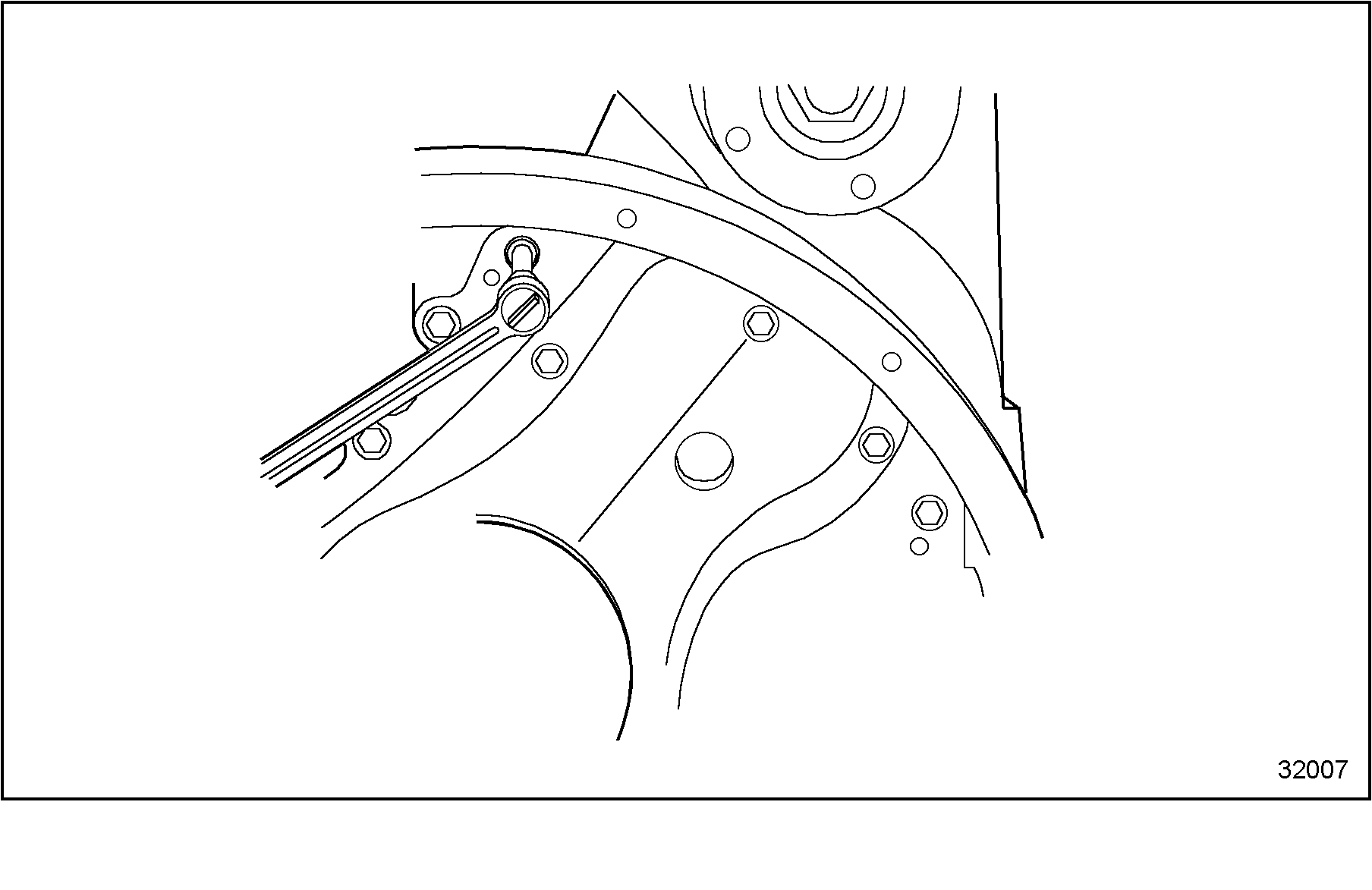
- Use a hex key to remove the special nut inside the rear PTO housing found under the pipe plug. Take care that the nut is not dropped into the housing. See Figure
"Special Nut Removal"
.

Figure 2. Special Nut Removal
- Remove the three mounting bolts from inside the rear PTO housing after the pipe plugs have been removed. See Figure
"PTO Mounting Bolts Removal"
.

Figure 3. PTO Mounting Bolts Removal
- Install the four pipe plugs back into the rear PTO housing.
- Remove the remaining four mounting bolts from the rear PTO housing assembly. Place an oil drain pan underneath rear PTO housing assembly. Approximately one quart of oil remains in the housing sump area.
- Pull the rear PTO housing assembly straight back, away from the crankcase.
- Remove one hollow dowel pin and four O-rings from the housing.
- Lay rear PTO housing assembly face down on the engine mounting surface side. Remove dowel guide pins. Some additional oil may drain from the housing as it is laid flat.
Section 9.1.2
Installation of Rear PTO Housing
Follow these steps to install the rear PTO housing.
- Lay the rear PTO housing assembly with the transmission side face down.
- Install one large O-ring and three small O-rings into the O-ring grooves using Aviation Permatex #3.
- Install two hollow dowel pins into rear PTO housing assembly
- Inspect threads and replace stud if necessary. Install stud into crankcase.
- Install the new camshaft O-ring over the camshaft end opening at the rear of the crankcase.
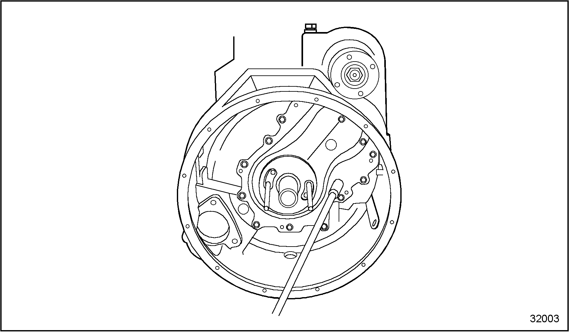
- Install two guide dowel pins, used during removal procedure, into the crankshaft flange at the 3 and 9 o'clock positions. See Figure
"Guide Pin Installation"
.

Figure 4. Guide Pin Installation
- If not removed already, remove the four pipe plugs from the rear PTO housing assembly.
- Lift the rear PTO housing assembly and align with the crankcase.
- Slowly guide the rear PTO housing assembly over the two guide pins mounted in the crankshaft and studs mounted in the crankcase. Install the seven mounting bolts and torque. Refer to Specifications "Additional Information"
in Section
. See Figure
"PTO Housing Installed Onto Crankcase"
.

1. Guide Pins
2. Installation Tool
Figure 5. PTO Housing Installed Onto Crankcase
- Install the special nut over the crankcase stud. See Figure
"Special Nut"
.

Figure 6. Special Nut
- Hand-tighten the special nut at the upper hollow dowel location. See Figure
"Tighten Special Nut"
.

Figure 7. Tighten Special Nut
- Torque the special nut to specifications. See Figure
"Install Pipe Plugs"
. Refer to Specifications "Additional Information"
in Section
.

Figure 8. Install Pipe Plugs
- Install the four pipe plugs and tighten.
- Remove lifting eye from rear PTO housing assembly.
- Install lubrication supply elbow and connect the lubrication supply tube to the crankcase and rear PTO housing assembly. Tighten the nuts securing the tube to the fittings. See Figure
"PTO Lubrication Tube"
.

1. Lubrication Tube
3. Elbow
2. Nut
Figure 9. PTO Lubrication Tube
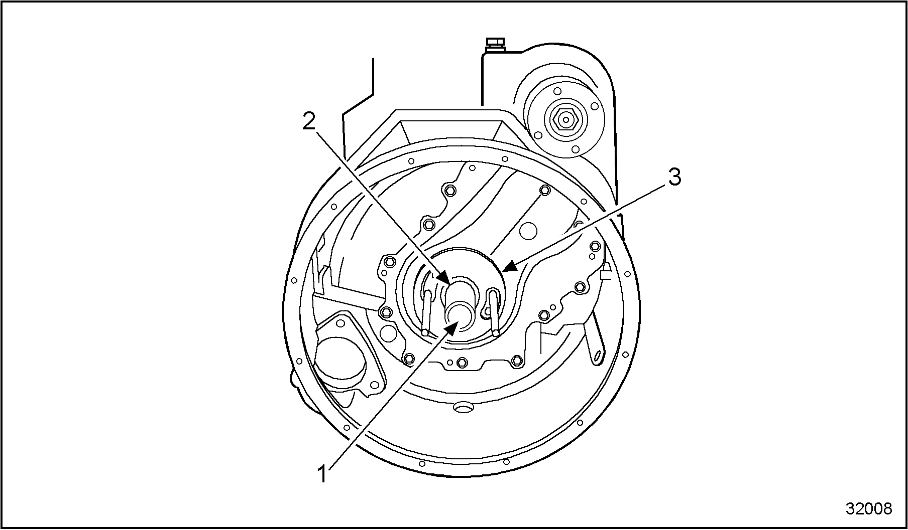
- Insert the steel rod of the installation tool through the hole of the tube assembly. See Figure
"Rear Oil Seal Installation Tool"
.

1. Steel Rod Location
3. Cover Assembly
2. Tube Assembly
Figure 10. Rear Oil Seal Installation Tool
- Pull out on the steel rod until the tube assembly comes out together with the cover assembly of the installation tool.
- Push the input gear towards the engine until the input gear reaches the mating surface of the crankshaft.
- Apply grease to the inner surface of the wear sleeve/rear oil seal before pressing it onto the input gear.
- Press the seal into the cover using the oil seal driver and a hammer.
| Series 40E Service Manual - 6SE410 |
| Generated on 10-13-2008 |