Section 2.37
Fuel Mixer for the Series 50G Engine With High Pressure Fuel System (Prior to 1998)
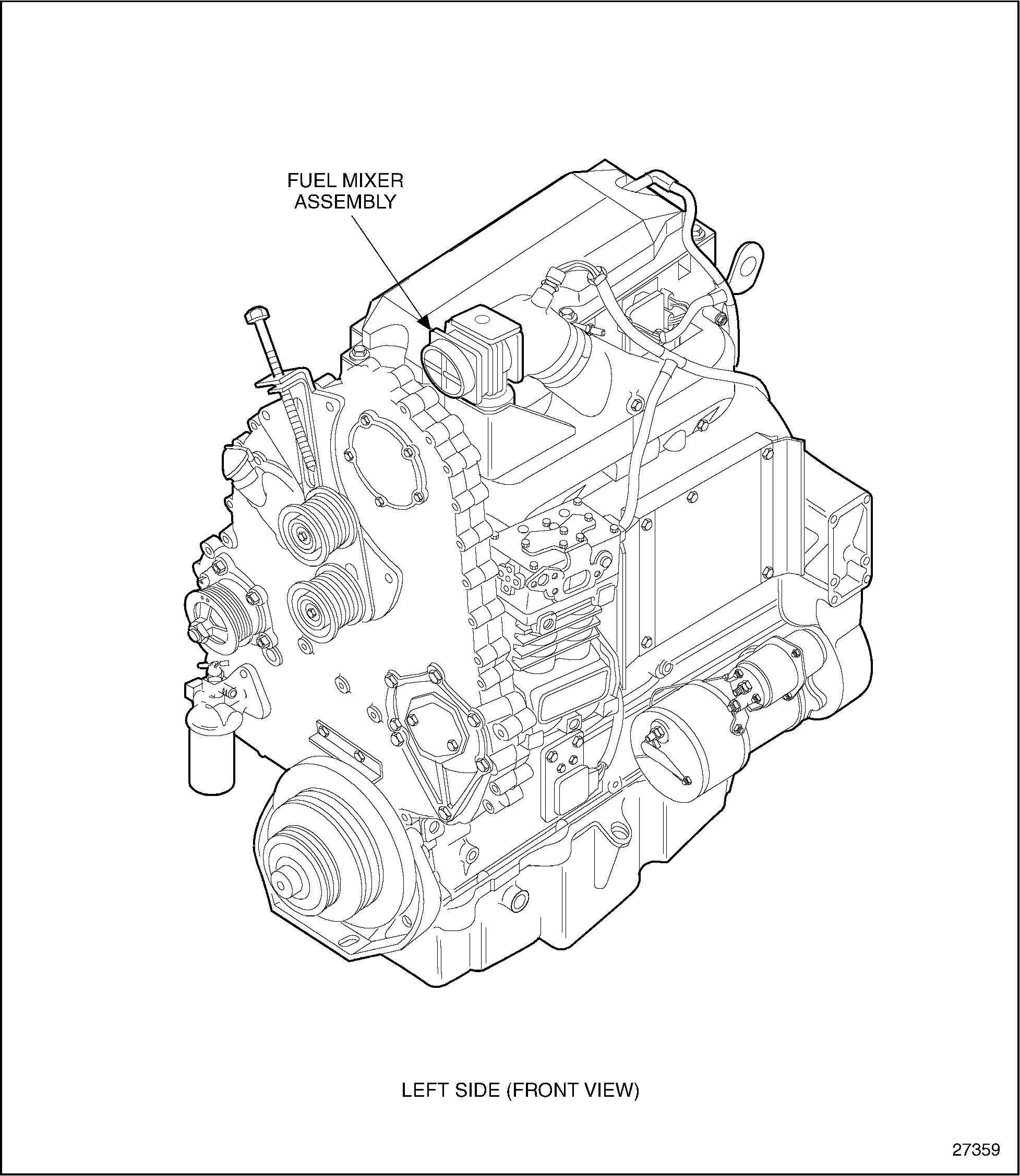
The fuel mixer assembly consists of a die cast aluminum body with a spun aluminum insert permanently installed. The unit has no moving parts. The mixer assembly is attached to the throttle on the left front side of the engine. See Figure "Fuel System (Series 50G Engine)" .

Figure 1. Fuel System (Series 50G Engine)
Section 2.37.1
Replacement of Fuel Mixer for the Series 50G Engine
The fuel mixer is non-serviceable and should be replaced as a unit. No adjustment is required.
Section 2.37.2
Removal of Fuel Mixer for the Series 50G Engine
Remove the fuel mixer as follows:
|
EXPLOSION |
|
To avoid injury from the explosion of natural gas, the engine must be kept in a well ventilated area away from open flames, sparks, and electrical resistance (heating) coils. |
- Vent fuel system; refer to "2.43.1 Venting an Operable Engine to Relieve Natural Gas Pressure" and refer to "2.43.2 Venting an Inoperable Engine to Relieve Natural Gas Pressure" .
- Disconnect gas inlet hose at mixer.
- Disconnect air inlet hose at mixer housing.
- Remove bolts attaching mixer housing to throttle.
- Separate and remove the fuel mixer from the throttle.
Section 2.37.3
Disassembly of Fuel Mixer for the Series 50G Engine
Disassembly of the fuel mixer is not required.
Section 2.37.4
Cleaning of Fuel Mixer for the Series 50G Engine
Cleaning of the fuel mixer is not required.
Section 2.37.4.1
Inspection of Fuel Mixer for the Series 50G Engine
Inspection of the fuel mixer is not required.
Section 2.37.4.2
Test of Fuel Mixer for the Series 50G Engine
Test of the fuel mixer is not required.
Section 2.37.5
Installation of Fuel Mixer for the Series 50G Engine
Install the fuel mixer as follows:
- Clean gasket surface and install a new gasket.
- Secure the fuel mixer to the throttle with four bolts. Torque to 20 N·m (15 lb·ft).
- Connect fuel inlet hose.

EXPLOSION
To avoid injury from an explosion of natural gas, the following precautions must be taken:
- Use a combustible-gas detector. Liquefied natural gas (LNG) is odorless and cannot be detected by smell. Compressed Natural gas (CNG) may be odorless and may not be detected by smell.
- Equipment fuel systems are the responsibility of the Original Equipment Manufacturer (OEM). Equipment fuel system guidelines must be closely adhered to when installing or servicing equipment. Refer to OEM guidelines specifying which maintenance procedures require venting of fuel lines and fuel tanks.
- LNG systems are pressurized and contain extremely cold (-162° C [-260° F]) fluids. Contact the fuel supplier or OEM for LNG safety requirements. Contact with LNG may cause personal injury (freezing).
- Vent systems on the equipment should be ducted to a safe area whenever equipment is in an enclosed area.
- Install air inlet hose and secure with V-band clamp. This hose must be of the current design that has a black interior surface. All former hoses have a blue interior surface and must be replaced. Also, the part number is printed on the exterior surface of the hose.
- Refer to "2.43.3 Leak Checking the Natural Gas Fuel System" for leak checking procedure.
| Series 50 Service Manual - 6SE50 |
| Generated on 10-13-2008 |