Section 6.1
Air Intake System Overview
The air intake system consists of the following components:
- Air cleaner
- Intake manifold
- Turbocharger diesel
- Turbocharger gas
- Charge air cooler
- Throttle Actuator (Series 50 Gas)
- Air dryer
Section 6.1.1
Air System for Series 50 Diesel
The turbocharger supplies air under pressure to the intake manifold. The air enters the turbocharger after passing through the air cleaner. Power to drive the turbocharger is extracted from energy in the engine exhaust gas. The expanding exhaust gases turn a single stage turbocharger wheel, which drives an impeller, thus pressuring intake air. This charge air is then cooled by an air-to-air heat exchanger before the engine intake manifold for improved combustion efficiency. See Figure "Air Intake System Schematic Series 50 Diesel" .
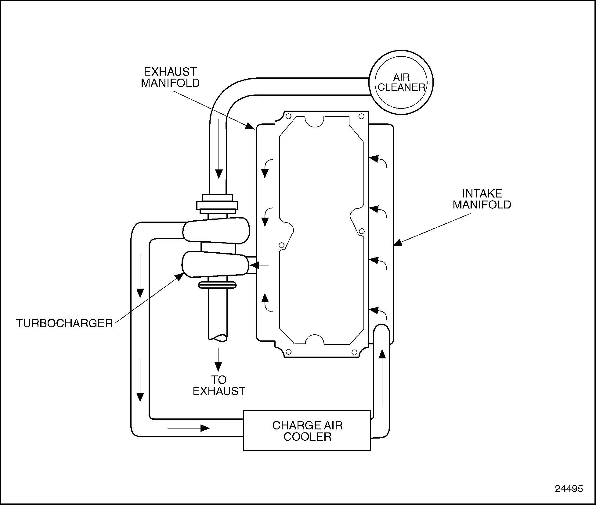
Figure 1. Air Intake System Schematic Series 50 Diesel
A charge air cooler (CAC) is mounted ahead or beside the engine coolant radiator. The pressurized intake charge is routed from the discharge side of the turbocharger, through the CAC to the intake manifold, which directs the air to ports in the cylinder head, through two intake valves per cylinder, and into each cylinder. At the beginning of the compression stroke, each cylinder is filled with clean air.
Repair and replacement procedures for the individual components of the air intake system are contained in this section.
Section 6.1.2
Air System for Series 50G (High Pressure)
The air system components on the Series 50G engine with high pressure fuel system are similar to the diesel engine air system except for the addition of a gas mixer and throttle, see Figure "Air Intake System Schematic Series 50G (High Pressure)" . The turbocharger for this engine is also different and features a turbine bypass (wastegate) and compressor recirculation valve. These features are described in more detail in the turbocharger section ; refer to "6.5 Turbocharger Series 50 Diesel" .

Figure 2. Air Intake System Schematic Series 50G (High Pressure)
In this system, air leaving the charge air cooler enters the mixer assembly and is mixed with a precisely controlled flow of natural gas. This combustible air fuel mixture then passes through the throttle and into the intake manifold. The throttle controls the flow of air-fuel mixture to the intake manifold thereby providing control over the power output of the engine. On automotive (bus) engines an oxygen sensor is installed within 12 inches of the turbocharger turbine exhaust outlet and adjacent to the exhaust temperature sensor. A harness connects the sensors to the ECM.
Section 6.1.3
Air System for Series 50G (Low Pressure)
The air system components on the Series 50G engine with low pressure fuel system are similar to the diesel engine air system except for the addition of a gas mixer and throttle; see Figure "Air Intake System Schematic 50G (Low Pressure)" . The turbocharger for this engine is also different and features a turbine bypass (wastegate) and compressor recirculation valve. These features are described in more detail in the turbocharger section. Refer to "6.5 Turbocharger Series 50 Diesel" .
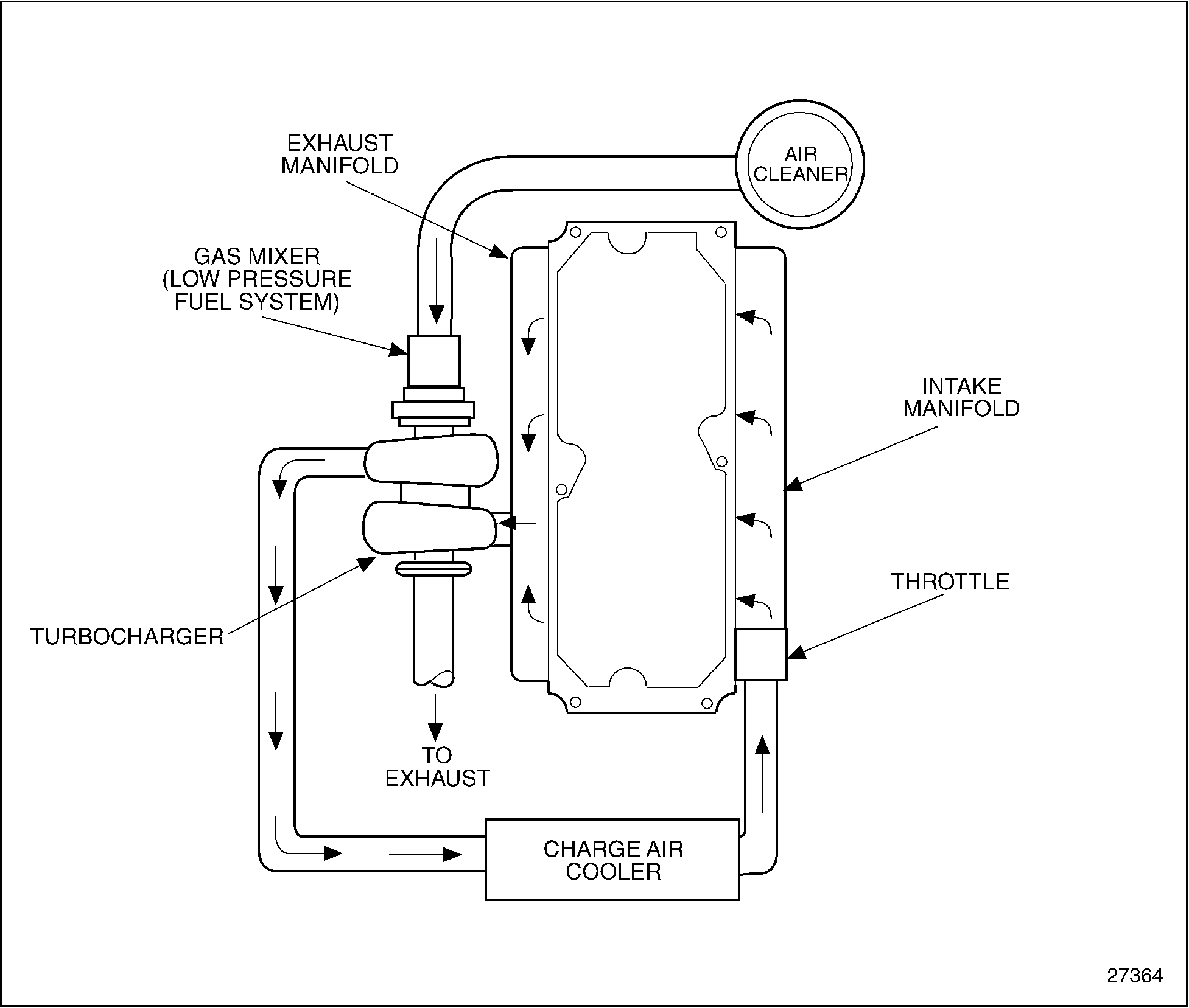
Figure 3. Air Intake System Schematic 50G (Low Pressure)
On engines with the low pressure fuel system air is drawn into the gas mixer ahead of the turbocharger. A precisely controlled flow of natural gas is mixed with the air and flows into the turbocharger where it is compressed before flowing through the charge air cooler. This combustible air fuel mixer then passes through the throttle and into the intake manifold. The throttle controls the flow of air-fuel mixture to the intake manifold thereby providing control over the power output of the engine.
| Series 50 Service Manual - 6SE50 |
| Generated on 10-13-2008 |