Section 12.2
Valve Lash, Injector Height (Timing) and Jake Brake ® Lash Adjustments
Accurate adjustment of clearance between valve buttons, intake and exhaust valves is important if maximum performance and economy are to be obtained.
Likewise, injector height should be properly maintained.
Intake valve clearance and injector height are adjusted by means of an adjusting set screw and locknut located at the valve (or injector) end of the rocker arm; see Figure "Valve and Fuel Injector Rocker Arm Assembly Components" .
Note: On engines equipped with a Jake Brake, measure valve lash and injector height before removing any brake housings. Only remove the brake housings necessary to provide access for adjustment.

|
1. Exhaust Valve |
6. Intake Valve |
|
2. Intake Valve |
7. Fuel Injector Follower |
|
3. Locknut |
8. Valve Button |
|
4. Adjusting Set Screw |
9. Exhaust Valve |
|
5. Exhaust Rocker Arm Assembly |
|
Figure 1. Valve and Fuel Injector Rocker Arm Assembly Components
NOTICE: |
|
Ensure the height gage seats on the machined surface with the tip in the pilot hole. Foreign material in the pilot hole or on the machined surface may prevent accurate setting of the injector height. |
The fuel injector height is adjusted using the injector height gage, as listed in Table "Valve Clearance and Injector Height Settings" . On engines equipped with a Jake Brake®, move the handle on the injector height gage to the alternate position, 90° to the shank. A height gage pilot hole is provided in the injector body on the machined surface contacted by the injector clamp near the solenoid. See Figure "Timing Gage" .
|
Component |
Setting Dimensions |
Tolerance |
|
Fuel Injector Height: DDEC II Models 6047 GUXX |
78.2 mm (3.078 in.) Use tool J 35637-A |
77.95-78.45 mm (3.068-3.088 in.) |
|
Fuel Injector Height: DDEC III Models 6047 GKXX |
78.8 mm (3.103 in.) Use tool J 39697 |
77.55-79.05 mm (3.053-3.112 in.) |
|
Fuel Injector Height: DDEC IV Model: 6047TKXX |
80.3 mm (3.161 in.) Use tool J 42665 |
80.05-80.55 mm (3.151-3.171 in.) |
|
Fuel Injector Height: DDEC IV Model: 6047MKXX |
81.0 mm (3.190 in.) |
|
|
Intake Valve Clearance |
0.203 mm (0.008 in.) |
0.127-0.280 mm (0.005-0.011 in.) |
|
Intake Valve Clearance Natural Gas Models 604XGKGX |
0.279 mm (0.011 in.) |
0.203-0.356 mm (0.008-0.014 in.) |
|
Intake Valve Clearance Model 604XMKGX |
0.267 mm (0.010 in.) |
0.253 -0.281 mm (0.009.-0.011 in.) |
|
Exhaust Valve Clearance*-"U" Valves Models 604XGUXX |
0.508 mm (0.020 in.) |
0.432-0.584 mm (0.017-0.023 in.) |
|
Exhaust Valve Clearance*-"H" Valves Models 604XGKXX |
0.660 mm (0.026) |
0.584-0.736 mm (0.023-0.029 in.) |
|
Exhaust Valve Clearance*-"J" All Natural Gas Models 604XXXGX |
0.914 mm (0.036 in.) |
- |
|
Exhaust Valve Clearance **_Nickel- Alloy Valves Models 604XMKXX, 604XTKXX |
0.508 mm (0.020 in.) |
0.432-0.584 mm (0.017-0.023 in.) |
XX Any characters in these positions set to the adjacent column.
* "U", "H", and "J" valves have the letter designation stamped in the recess of the valve head. "H" and "J" valves also have a machined identification ring above the valve lock groove. "U" valves do not.
** After engine serial number 4R37769 the valve is identified by the raised bump in the center of the recess on the combustion face, the deletion of the machined identification ring above the keeper groove and the part number.
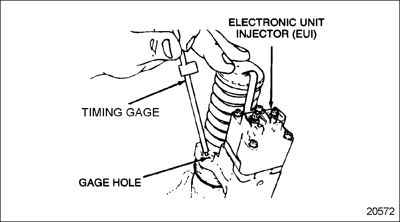
Figure 2. Timing Gage
To determine if improper valve clearance, injector height or both are causing the cylinder to misfire, perform the following preliminary step 1 through step 3 and repeat step 4 through step 12 for each cylinder to determine if worn or damaged lobes or rollers are causing the engine to misfire:
- Disconnect starting power for engine.
- Remove the engine valve rocker cover. Refer to "1.6.2 Cleaning and Removing of Two-piece Rocker Cover-Diesel Engines Only" . .
- Insert a 3/4 in. drive breaker bar or ratchet into the square hole in the center of the crankshaft pulley.
- Bar the engine over. Stop engine rotation when any one of the injector followers has just begun its downward stroke; see Figure
"Injector Followers Downward Stroke"
.

1. Injector Follower
4. Injector Cam Lobe
2. Injector Rocker Arm Assembly
3. Injector Roller
5. Point on the Camshaft Lobe that first produces downward motion of the injector follower
Figure 3. Injector Followers Downward Stroke
- Using the Timing Circle Chart, see Figure
"Timing Circle Chart"
, locate the cylinder requiring clearance. The timing circle can be started with any cylinder. Ensure that the circle is completed to adjust all valves and injectors.

Figure 4. Timing Circle Chart
NOTICE:
Never set the valves and injector of the same cylinder at the same time. Doing this will result in engine damage.
- For diesel applications adjust the intake valves, insert a feeler gage between the tip of the valve stem and the valve button at the end of the rocker arm. See Figure "Valve Clearance Adjustment" and see Table "Valve Clearance and Injector Height Settings" .
- For natural gas applications adjust the intake valves, insert a feeler gage between the tip of the valve stem and the valve button at the end of the rocker arm. See Table "Valve Clearance and Injector Height Settings" .
- Loosen the locknut, and turn the adjusting set screw until the feeler gage produces an even smooth pull between the valve stem and valve button.

1. Feeler Gage
4. Wrench (9/16 in.)
2. Valve Button
5. Intake Valve Stem
3. Allen Wrench (3/16 in.)
Figure 5. Valve Clearance Adjustment
- Torque the locknut to 41-47 N·m (30-35 lb·ft) and remove the feeler gage. Reinsert the feeler gage to ensure that the adjustment did not change when the locknut was tightened. Readjust as necessary.
- For diesel applications the exhaust valves are adjusted the same way as the intake valves. See Table
"Valve Clearance and Injector Height Settings"
.
After engine serial number 4R37769 use a 0.5080 mm (0.020 in.) feeler gage. Check option label on valve cover for correct settings. It is normal for tune-up settings to vary, even when using the correct setting procedures. Some items influencing tune-up measurements are different gages, individuals and mechanical variations.
Note: When setting valve lash clearance or injector height, always set them to the dimensions listed in Table "Valve Clearance and Injector Height Settings" .
- For natural gas applications the exhaust valves are adjusted the same way as the intake valves. See Table "Valve Clearance and Injector Height Settings" .
- Complete the adjustment of all four valves (two intake, two exhaust) for that cylinder before proceeding to step 13 .
- Refer to the Timing Circle Chart and note the cylinder number in parentheses, directly under the cylinder that just received the valve lash adjustment. See Figure "Timing Circle Chart" .
- Adjust the fuel injector height for the cylinder indicated on the chart in parentheses, see Figure
"Timing Circle Chart"
, by placing the small end of the height gage in the hole provided in the fuel injector body, with the flat of the gage toward the fuel injector plunger. See Figure
"Fuel Injector Height Adjustment"
. Set injectors to the dimensions listed in Table
"Valve Clearance and Injector Height Settings"
.
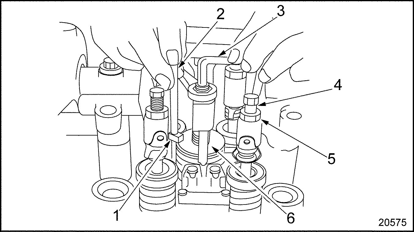
1. Height Gage Flag
4. Set Screw
2. Height Gage
5. Locknut
3. Allen Wrench (3/16 in.)
6. Fuel Injector Follower
Figure 6. Fuel Injector Height Adjustment
- Loosen the fuel injector rocker arm locknut and turn the adjusting set screw until the extended part (flag) of the gage will just pass over the top of the injector follower. An accurate "feel" will be developed. The objective is to adjust all four injectors to the same feel.
- Torque the locknut to 41-47 N·m (30-35 lb·ft). Check the adjustment with the height gage and, if necessary, readjust the set screw. Remove the height gage.
- Refer to the Timing Circle Chart. See Figure "Timing Circle Chart" and follow the arrow to the next cylinder in the adjustment sequence.
- Bar the engine over in the direction of normal rotation until the injector follower of the next cylinder in the adjustment sequence begins its downward motion, see Figure
"Injector Followers Downward Stroke"
.
1. Injector Follower
4. Injector Cam Lobe
2. Injector Rocker Arm Assembly
5. Point on the Camshaft Lobe that first produces downward motion of the injector follower
3. Injector Roller
Figure 7. Injector Followers Downward Stroke
- Repeat the valve adjustment and fuel injector height adjustment step 5 through step 17 until all the valves and fuel injectors have been adjusted.
- If the engine is equipped with Jake Brakes®, adjust Jake brake slave pistons. Refer to "1.30.5.1 Adjustment of Slave Piston" .
- Replace the engine rocker cover. Refer to "1.6.1 Repair or Replacement of Rocker Cover" .
- Reconnect starting power to the engine.
| Series 50 Service Manual - 6SE50 |
| Generated on 10-13-2008 |
engine coughed a couple of times at idle, but truck drove for a while. parked at wendys, and engine quit on its own.
Came out and gave a shot of ether, and engine caught, but didn’t start on fuel.
ANY SUGGESTIONS ?