Section 11.2
Air Compressor Drive Hub
The air compressor crankshaft will turn while removing or tightening the drive hub retaining nut unless some provision is made to hold it. One method is to weld a modified drive coupling to a support or base which can be anchored to the mounting flange of the compressor.
A Series 71 or 92 flywheel housing cover that matches the flange of the compressor makes an ideal base for the modified coupling. When positioned, the exterior splines of the coupling mesh with the internal splines of the drive hub and the assembly is secured to the compressor housing. The shaft is then kept from rotating when the nut is loosened or tightened, by the hub and key.
Section 11.2.1
Replacement of Air Compressor Drive Hub
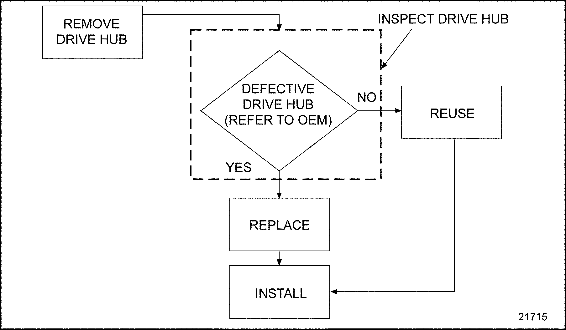
To replace the air compressor drive hub, perform the following procedure. See Figure "Flowchart for Replacement of Air Compressor Drive Hub" .

Figure 1. Flowchart for Replacement of Air Compressor Drive Hub
Section 11.2.2
Removal of Air Compressor Drive Hub
To keep the shaft from rotating, perform the following:
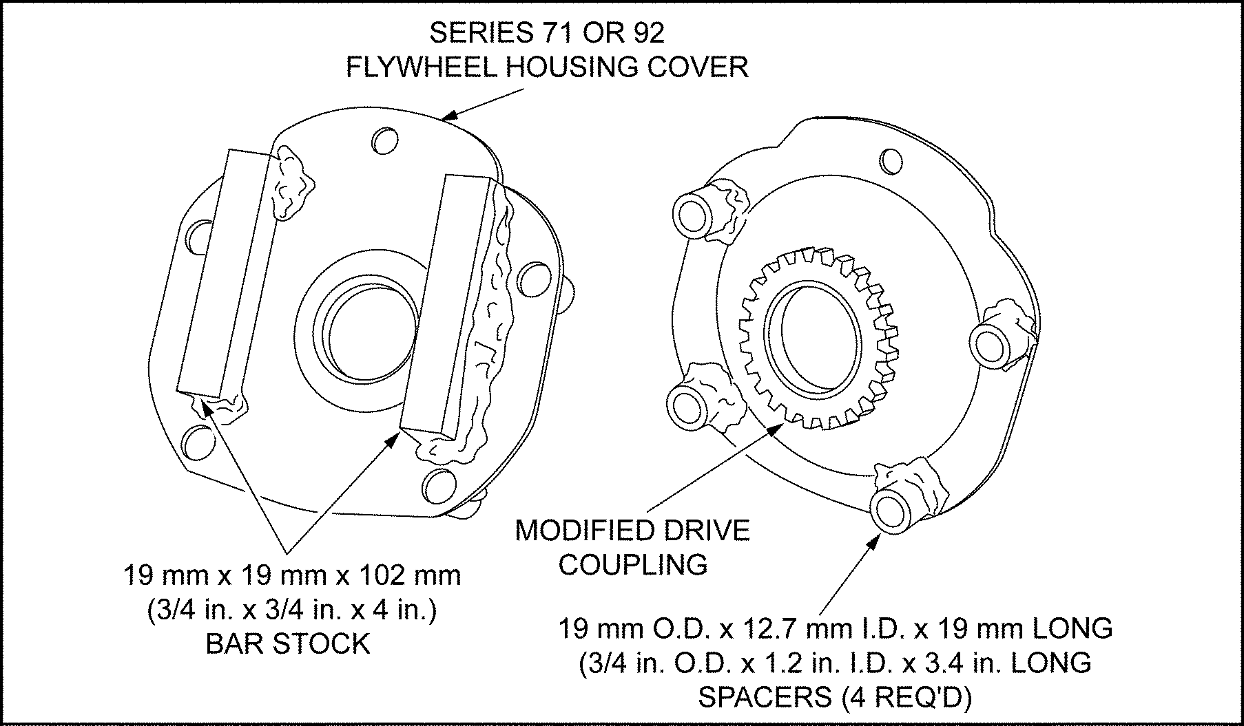
To properly position the cover and coupling with the drive hub, four collars, 19 mm O.D. and 12.7 mm I.D., 19 mm long (0.75 in. O.D. and 0.50 in. I.D., 0.75 in. long), and two pieces of bar stock 19 mm x 19 mm x 102 mm (0.75 in. x 0.75 in. x 4.0 in.) must be fabricated and welded to the flywheel housing cover at the positions shown in the next illustration. See Figure "Holding Fixture " .

Figure 2. Holding Fixture
Position the coupling into the drive hub. Lay the flywheel housing cover over the coupling, center the collars over the compressor housing bolt holes, and tack weld the cover to the coupling.
The diameter of the cover hole must be opened up to the same diameter as the coupling inside diameter to permit access to the drive hub retaining nut. Two bolts will secure the base to the compressor during the operation.
Remove the air compressor drive hub as follows:
- Install the holding fixture to the flange of the air compressor, engaging the coupling with the internal teeth of the drive hub. Install two bolts to secure the fixture to the compressor. See Figure
"Air Compressor Crankshaft Holding Fixture Installation"
.

Figure 3. Air Compressor Crankshaft Holding Fixture Installation
- Loosen and remove the drive hub retaining nut.
- Remove the drive hub from the air compressor by lifting the hub off the shaft.
Section 11.2.3
Inspection of Air Compressor Drive Hub
Refer to OEM guidelines to determine if the air compressor drive hub needs to be repaired or replaced.
Section 11.2.4
Installation of Air Compressor Drive Hub
Install the air compressor drive hub as follows:
NOTICE: |
|
The drive hub and nut on the Series 60 engine have a unique configuration. Only the correct part numbers should be used. |
- Install the hub to the shaft as far as it will go by hand. Do not cock or jam the hub. See Figure
"Air Compressor Drive Hub Assembly"
.

Figure 4. Air Compressor Drive Hub Assembly
- Install the drive holding fixture to the flange of the air compressor, engaging the coupling with the internal teeth of the drive hub. Install two bolts to secure the fixture to the compressor. See Figure "Air Compressor Crankshaft Holding Fixture Installation" .
- Torque the air compressor drive hub retaining nut to 300-345 N·m (220-255 lb·ft). See Figure
"Torquing Drive Hub Retaining Nut"
.

Figure 5. Torquing Drive Hub Retaining Nut
- Loosen the two bolts that retain the holding fixture to the compressor flange, and remove the holding fixture.
| Series 60 Service Manual - 6SE483 |
| Generated on 10-13-2008 |