Section 20.11
Miscellaneous Digital Input Fault
The following procedure will cover miscellaneous input switch faults. All faults function in the same manner, allowing the same troubleshooting process to be used regardless of the function.
There are 12 digital input cavities, listed in Table "Input Cavities" , available on a DDEC ECM/ECU. Any available function can be assigned (programmed with the Programming Station) to any of the available cavities.
|
Input Cavities |
Input Cavities |
|
V–41 |
V–01 |
|
V–25 |
V–50 |
|
V–24 |
V–10 |
|
V–42 |
V–05 |
|
V–47 |
V–08 |
|
V–09 |
V–39 |
When a digital input wire is switched to battery ground (usually V-59), it is a request to the ECM/ECU to activate the function assigned to that wire. Available functions are listed in Table "Available Input Functions" .
|
Functions |
Functions |
Functions |
|
Engine Brake Disable |
Limiting Torque Curve |
Trans Retarder Status |
|
Engine Brake Low |
Diagnostic Request |
Dual Throttle (LSG) |
|
Engine Brake Med |
Alt Min VSG/Fast Idle |
A/C Fan Status |
|
Aux Shutdown #1 |
Service Brake Release |
Aux CLS/ECL Sensor |
|
Aux Shutdown #2 |
Clutch Released |
Fan Control Override |
|
Park Brake / ISD |
Set / Coast ON |
VSG Station Change |
|
Idle Validation |
Resume / Accel ON |
VSG Station Complement |
|
Pressure / RPM Mode |
Cruise Enable |
Air Load Switch |
|
Throttle Inhibit |
PSG System Enable |
In Neutral Switch |
|
Rating Switch #1 |
SEO / DIAG Request |
In Gear Switch |
|
Rating Switch #2 |
Gas Valve Diagnostic |
KD Brake |
Additional conditions may need to be met for the feature to activate. Refer to the DDEC V Application and Installation (7SA821) manual for these conditions. This manual is available on the DDC Extranet.
Section 20.11.1
Verify Switch Status
Follow these steps to verify the switch status.
- Turn ignition ON.
- Plug in DDR.
- Select switch light status.
- Operate the engine or vehicle that would allow the feature to activate (e.g. activate switch, set brake, etc.).
- Observe the status when the feature is active (or supposed to be active). See Figure
"ECM/ECU-to-Input / Sensor Return"
.
- The feature always reads OFF. Refer to "20.11.2 Check for Open" .
- The feature switches from OFF to ON. Refer to "20.11.3 Review the Operation of the Feature" .
- The feature always reads ON. This indicates the input wire is shorted to ground or the switch is faulty. Repair wire or replace switch. Refer to "20.11.3.1 Verify Repairs" .
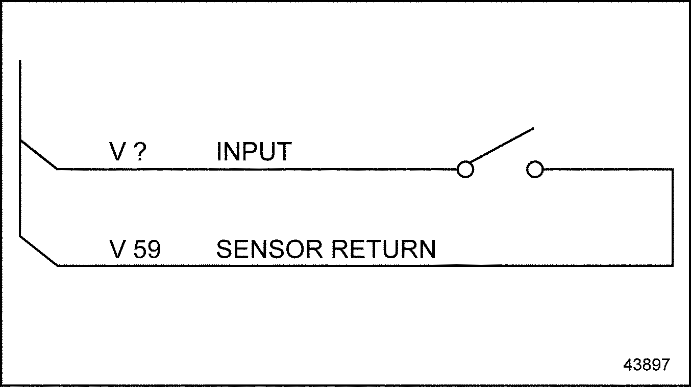
Figure 1. ECM/ECU-to-Input / Sensor Return
Section 20.11.2
Check for Open
Perform the following steps to check for an open:
- Turn ignition OFF.
- Unplug the vehicle interface harness connector at the ECM/ECU.
- Operate switch. Enable the feature.
- Measure the resistance between the input cavity affected and the battery ground.
- If the measured resistance is greater than 10,000 Ω, the input wire or ground wire is open, or the switch is bad. Repair the open or replace the switch. Refer to "20.11.3.1 Verify Repairs" .
- If the measured resistance is less than 10,000 Ω, refer to "20.11.3 Review the Operation of the Feature" .
Section 20.11.3
Review the Operation of the Feature
Perform the following steps to check the operation of the feature:
- The step that led you here indicates the input, wire, and switch, are operating correctly. Review the intended operation of the feature to determine if any other conditions need to be met for the feature to operate. (e.g. DDEC V Application and Installation manual available on the DDC extranet).
- To verify the repairs to the feature, refer to "20.11.3.1 Verify Repairs" .
Section 20.11.3.1
Verify Repairs
Perform the following steps to verify repairs.
- Hook up all connectors that were previously removed.
- Operate the engine or vehicle.
- Activate the feature.
- If the input feature operates correctly, troubleshooting is complete.
- If the input feature is not operating, contact Detroit Diesel Customer Service Center (313-592-5800) .
| Series 60 DDEC V Troubleshooting Guide - 6SE570 |
| Generated on 10-13-2008 |