Section 132.2
SPN 4258/FMI 4
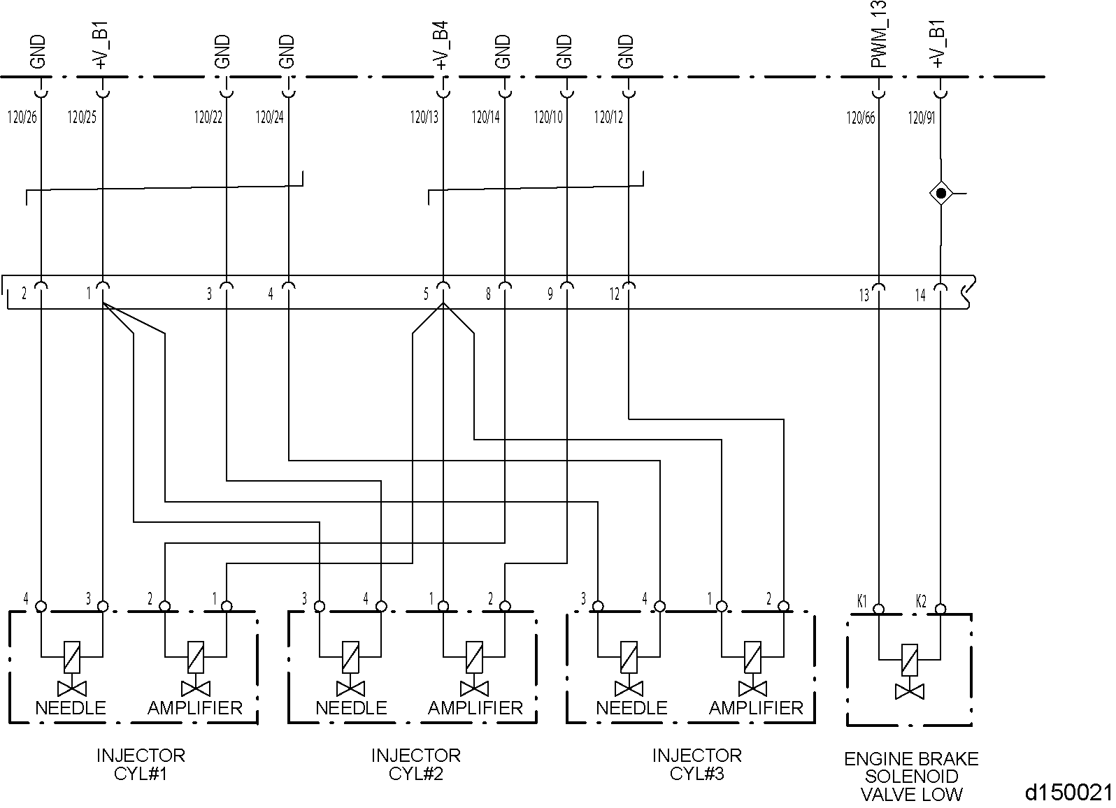
This diagnosis is typically injector #1, 2, or 3 amplifier control valve circuit is shorted to ground.
Check as follows:
- Disconnect the Front Injector Harness 14–pin connector.
- Inspect the Front Injector Harness 14–pin connector for bent or spread pins, inspect the connector seal for damage (signs of water or oil intrusion).
- If the water or oil intrusion, bent or spread pins are found, repair as necessary. Refer to "132.2.1 Verify Repairs" .
- If connector shows no signs of damage, go to the next step.
- Measure the resistance between pin 5 on the valve cover side of the Front Injector Harness 14–pin connector and ground. If you are using J-48671–10
, measure between injector #1 pin 1 and ground.

- If the resistance is greater than 3 Ω, go to step 11 .
- If the resistance is less than 3 Ω, go to the next step.
- Remove the upper valve cover.
- Disconnect injector #1.
- Measure the resistance between pin 5 on the valve cover side of the Front Injector Harness 14–pin connector and ground. If you are using J-48671–10
, measure between injector #1 pin 1 and ground.
- If the resistance is greater than 3 Ω, replace injector #1. Refer to "132.2.1 Verify Repairs" .
- If the resistance is less than 3 Ω, go to the next step.
- Disconnect injector #2.
- Measure the resistance between pin 5 on the valve cover side of the Front Injector Harness 14–pin connector and ground. If you are using J-48671–10
, measure between injector #2 pin 1 and ground.
- If the resistance is greater than 3 Ω, replace injector #2. Refer to "132.2.1 Verify Repairs" .
- If the resistance is less than 3 Ω, go to the next step.
- Disconnect injector #3.
- Measure the resistance between pin 5 on the valve cover side of the Front Injector Harness 14–pin connector and ground. If you are using J-48671–10
, measure between injector #3 pin 1 and ground.
- If the resistance is greater than 3 Ω, replace the #3 injector. Refer to "132.2.1 Verify Repairs" .
- If the resistance is less than 3 Ω, replace the under valve cover injector harness. Refer to "132.2.1 Verify Repairs" ..
- Disconnect the 120–pin MCM connector.
- Measure the resistance between pin 5 of the harness side of the Front Injector Harness 14–pin connector and ground.
- If the resistance is greater than 3 Ω, go to the next step.
- If the resistance is less than 3 Ω, repair the short to ground between pin 13 of the MCM 120–pin connector and pin 5 of the Front Injector Harness 14–pin connector. Refer to "132.2.1 Verify Repairs" .
- Measure the resistance between pin 8 of the harness side of the Front Injector Harness 14–pin connector and ground.
- If the resistance is greater than 3 Ω, go to the next step.
- If the resistance is less than 3 Ω, repair the short to ground between pin 14 of the MCM 120–pin connector and pin 8 of the Front Injector Harness 14–pin connector. Refer to "132.2.1 Verify Repairs" .
- Measure the resistance between pin 9 of the harness side of the Front Injector Harness 14–pin connector and ground.
- If the resistance is greater than 3 Ω, go to the next step.
- If the resistance is less than 3 Ω, repair the short to ground between pin 10 of the MCM 120–pin connector and pin 9 of the Front Injector Harness 14–pin connector. Refer to "132.2.1 Verify Repairs" .
- Measure the resistance between pin 12 of the harness side of the Front Injector Harness 14–pin connector and ground.
- If the resistance is greater than 3 Ω, replace the MCM.
- If the resistance is less than 3 Ω, repair the short between pin 12 of the MCM 120–pin connector and pin 12 of the Front Injector Harness 14–pin connector.
Section 132.2.1
Verify Repairs
Verify repairs as follows:
- Turn ignition OFF.
- Reconnect any electrical connections that were disconnected to perform the diagnosis.
- Clear codes with DDDL 7.0 or latest version.

ENGINE EXHAUST
To avoid injury from inhaling engine exhaust, always operate the engine in a well-ventilated area. Engine exhaust is toxic.
- Start and bring engine up to operating temperature (over 140°F/60°C).
- Verify operation is satisfactory and no warning lamps illuminate. If warning lamps illuminate, troubleshoot the codes. If assistance is required, call the Detroit Diesel Customer Support Center at 313–592–5800.
| EPA07 DD15 Troubleshooting Guide - DDC-SVC-MAN-0029 |
| Generated on 10-13-2008 |