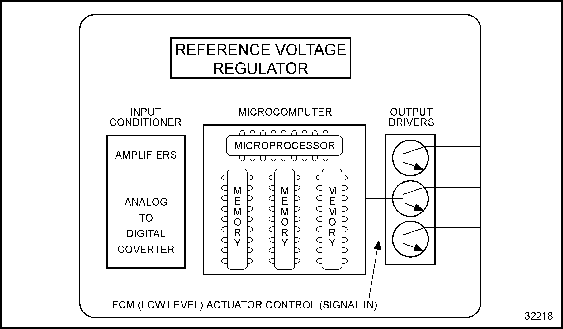
The ECM controls the actuators by applying a (low level) signal to the base of the transistor output drivers. These drivers, when switched on, will complete the ground circuit of each actuator.
The actuators are controlled through a duty cycle (% time on/off), a controlled pulse width, or simply switched on or off as determined by the type of actuator being controlled. See Figure
“Electronic Control Module Actuator Control”
.

Figure 1. Electronic Control Module Actuator Control
Section 5.2.1
Electronic Distributor for the Injectors
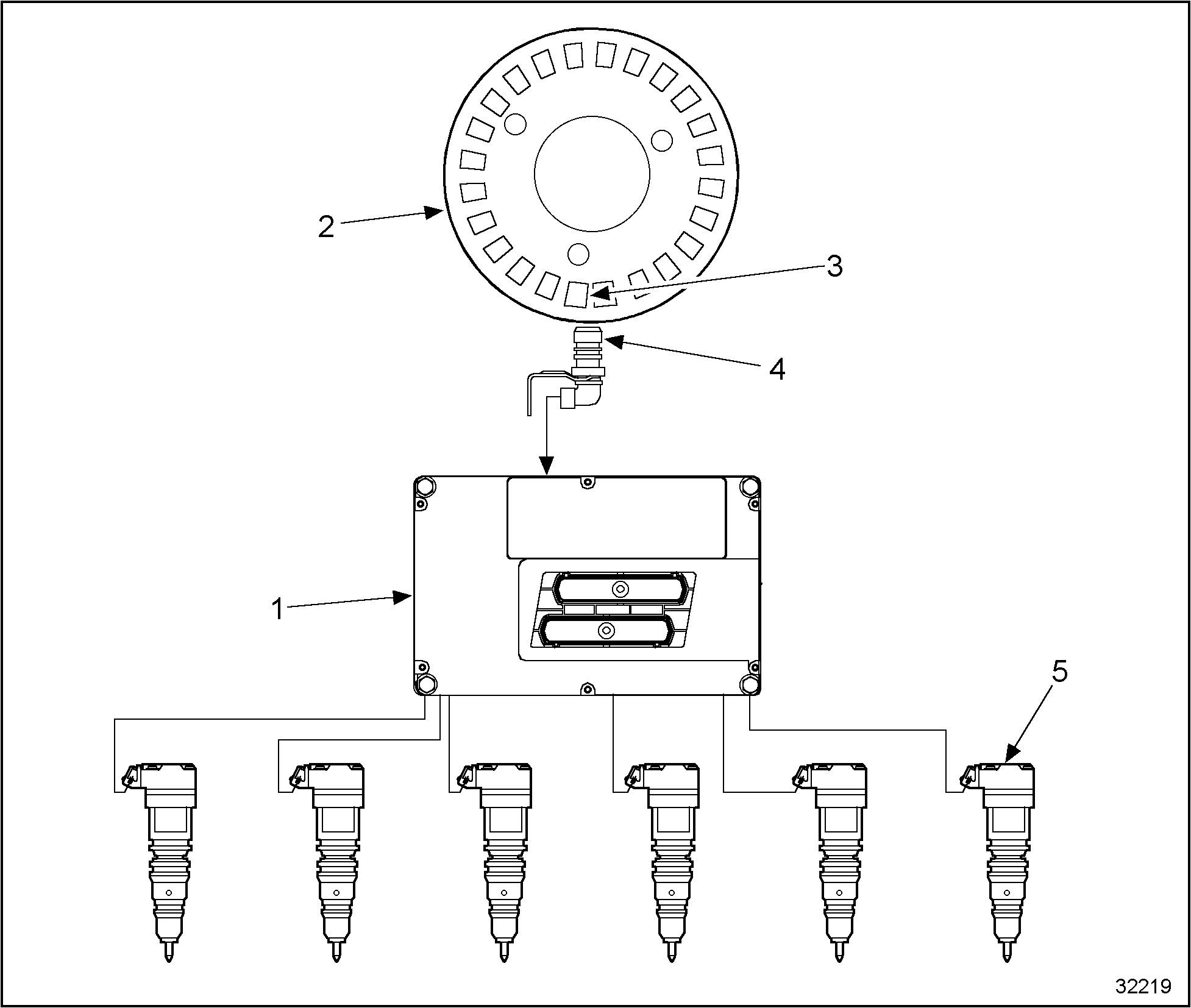
The ECM monitors the engine speed and cylinder positions by constantly monitoring the camshaft position signal. When the ECM senses the narrow vane of the trigger wheel through the CMP signal, it locates the position of the piston on cylinder No. 1 and based on that cylinder, the rest of the pistons. See Figure
“Electronic Distributor For Injectors”
.

| 1. ECM | 4. CMP Sensor |
| 2. Timing Sensor Disk | 5. Injectors |
| 3. Narrow Vane | |
Figure 2. Electronic Distributor For Injectors
Section 5.2.2
Ground Source
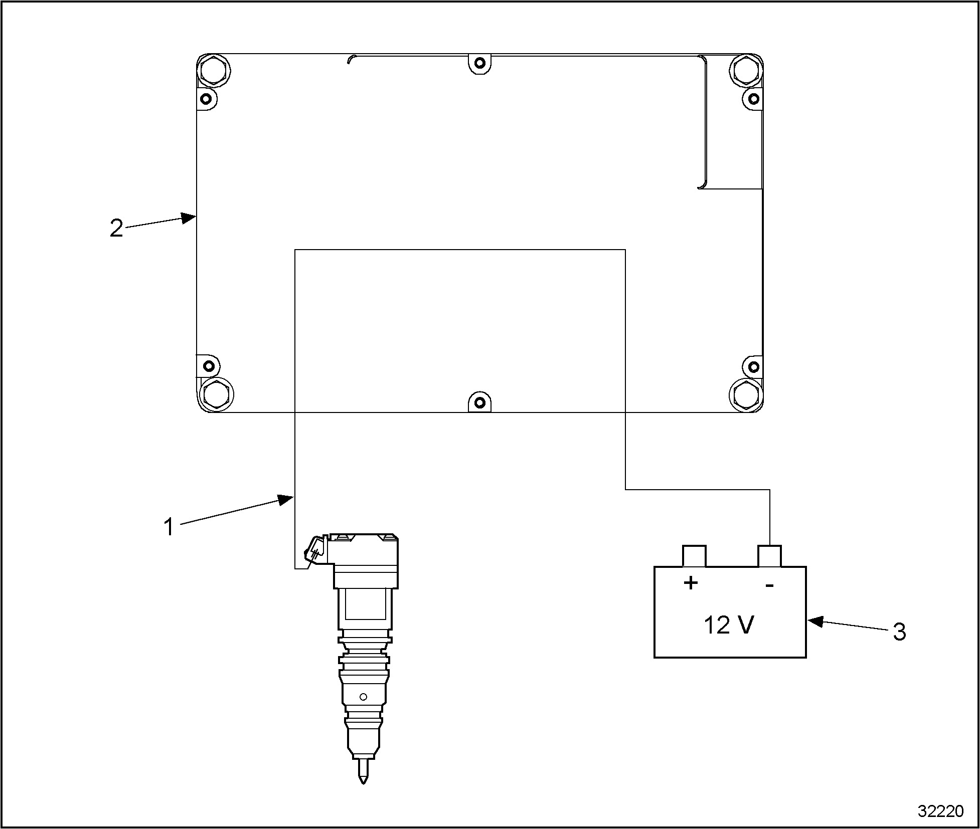
The ECM provides a constant ground path to all the injectors. See Figure
“Injector Ground Supply”
.

| 1. Supply Ground | 3. Battery Voltage |
| 2. ECM | |
Figure 3. Injector Ground Supply
Section 5.2.3
Power Source and Output Drivers
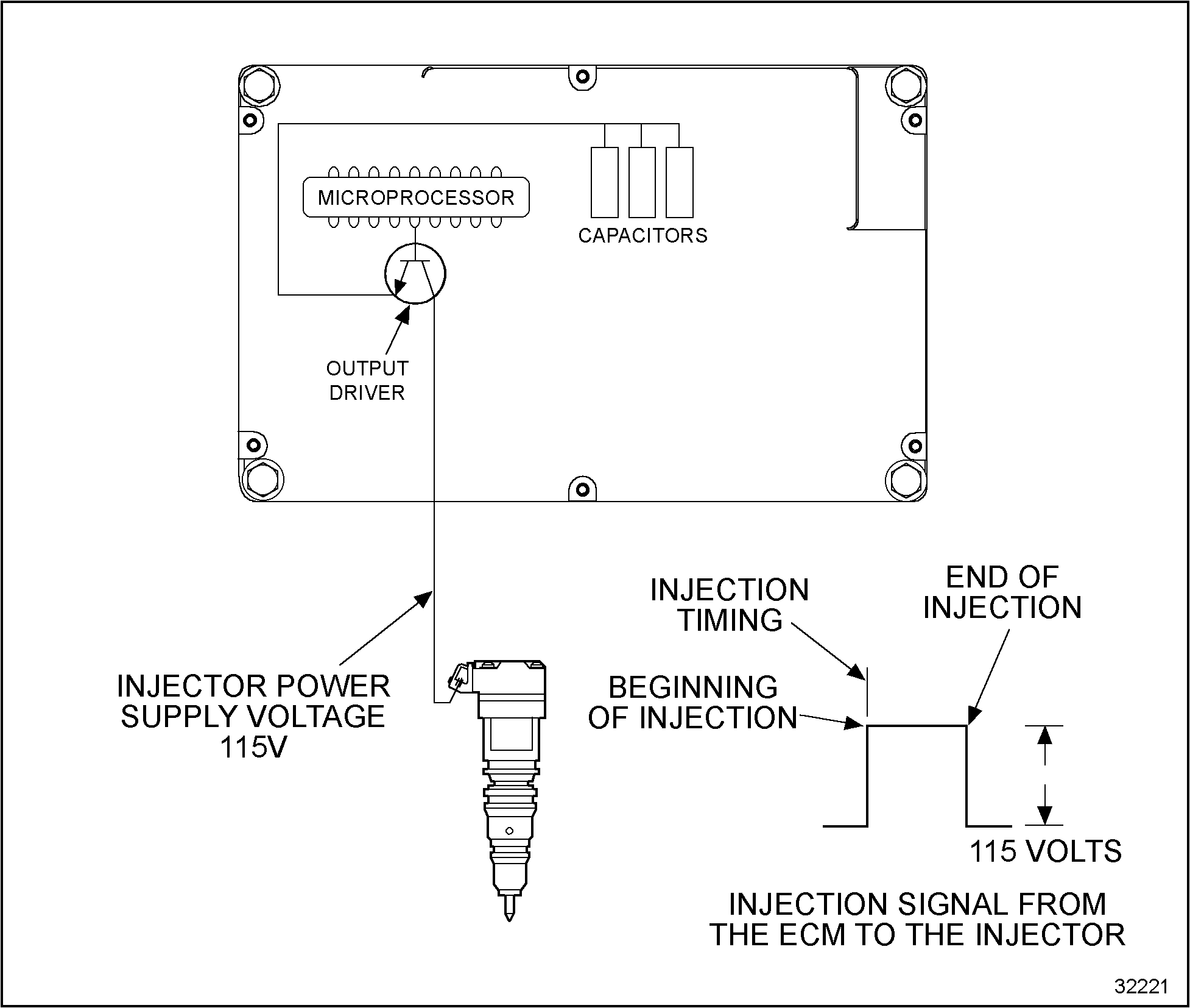
By using output driver transistors, the ECM supplies 115+ volts DC to each injector following the firing order. The ECM contains an individual output driver for each of the injectors. See Figure
“Injector Control High Side”
.
The processor of the ECM determines the following:
- The correct firing sequence
- The timing of the injectors
- The duration of the injection
Note: The 115+ volt DC supply is created by the ECM by making and breaking a 12 volt source across an internal coil, based on the same principle as the automotive ignition coil.

Figure 4. Injector Control High Side
| Series 40E Troubleshooting Manual – 6SE241 |
| Generated on 10-13-2008 |