Section 2.7
Fuel Filters (Spin-On)
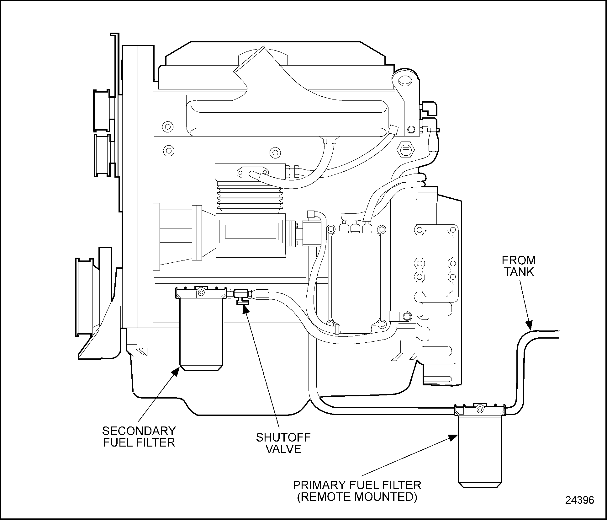
Two spin-on type filters are used on the Series 50 engine. The first in the fuel flow is a strainer, and the second is a filter. Although they are not marked as such, the threaded sleeves that accept the cartridges are different sizes to prevent mismatching. The primary filter has a 1 in. x 12 thread. The secondary filter has a 13/16 in. x 12 thread. The word "Primary" or "Secondary" is cast into the top of the respective adaptor. See Figure "Fuel Filters" .

Figure 1. Fuel Filters
The spin-on filter cartridges consist of a shell, element, and gasket combined into a unitized replacement assembly. No separate springs or seats are required to support the filters. Effective with 1993 engine production, an optional fuel filter/water separator assembly may be installed in place of the strainer. A fuel shutoff valve or check valve may be installed on the outlet side of the secondary filter.
The fuel filter system consists of the following:
- Spin-on primary fuel filter
- Primary fuel filter adaptor
- Spin-on secondary fuel filter
- Secondary fuel filter adaptor
- Fuel shutoff valve or check valve
Section 2.7.1
Replacement of Fuel Filter
As contaminants build up on the filter medium, a number of factors start to affect vehicle performance:
- The fuel delivery rate is reduced, making less fuel available for combustion.
- The fuel pump is forced to work harder to move the same volume of fuel. This subjects internal seals to abnormal conditions which may lead to seal leakage. In extreme cases air can be drawn into the fuel system.
- With the rate of flow slowed, fuel stays in the cylinder head for a longer period of time, allowing its temperature to rise above normal. Because fuel temperature has an affect on engine power, higher fuel temperatures normally result in reduced power.
- If the restriction is severe enough, fuel vaporization can occur, resulting in pockets of air that can further reduce fuel delivery.
All of these conditions can lead to power loss and subsequent operator complaints of "low power" and "reduced vehicle fuel economy" caused by the need to downshift more frequently on grades.
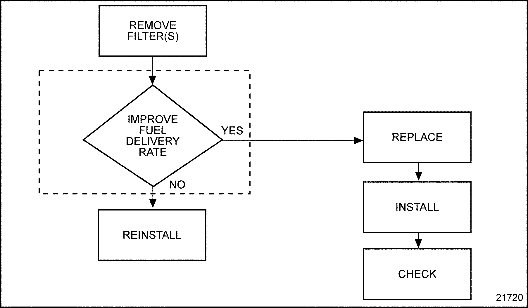
To determine if replacement of fuel filter element is necessary. See Figure "Flowchart for Replacement of Fuel Filter Element" .

Figure 2. Flowchart for Replacement of Fuel Filter Element
To replace the filter, perform the following steps:
- Use a suitable band wrench or filter wrench, such as J 22775 , to remove the filter(s).
- To install, fill the new filter replacement cartridges with clean fuel oil. Coat the gaskets slightly with clean fuel oil.
NOTICE:
Mechanical tightening of the fuel filters is not recommended, and may result in seal damage, cartridge damage, or both. Tighten the fuel filters by hand only.
- Thread the new filters on the adaptor, turning them until they contact the gasket fully with no side movement of the filter evident; then turn an additional one-half turn by hand, or as indicated on the filter cartridge.
NOTICE:
Do not overtorque the external threaded end of the shutoff valve when installing it in the fuel filter adaptor. The connection must be tight enough to prevent leakage but not tightened to the point where the adaptor will crack.
Note: There is a fuel system shutoff valve on the discharge side of the secondary fuel filter. This valve is designed to prevent loss of fuel prime at time of filter replacement.

PERSONAL INJURY
Diesel engine exhaust and some of its constituents are known to the State of California to cause cancer, birth defects, and other reproductive harm.
- Always start and operate an engine in a well ventilated area.
- If operating an engine in an enclosed area, vent the exhaust to the outside.
- Do not modify or tamper with the exhaust system or emission control system.
- Start the engine and check for leaks.
| Series 50 Service Manual - 6SE50 |
| Generated on 10-13-2008 |