Section 2.48
Overview of the Low Pressure Natural Gas Fuel System
The purpose of the fuel system is to store the fuel, keep it clean and free from air, water, or other impurities and to deliver it to the combustion chamber at the correct pressure, temperature, air and fuel mixture. The Series 60G engine requires an adequate fuel supply for proper performance and to develop full-rated power. This section describes the Detroit Diesel Series 60G compressed natural gas fuel system.
The following are DDC supplied parts:
- Pulse width modulated stepper motor valve (PSV)
- Low pressure regulator
- Venturi fuel mixer
- Regulator hoses
- Air inlet tube
The following are OEM supplied parts:
- Gas inlet pipe
- Genset controlled gas shutoff valve
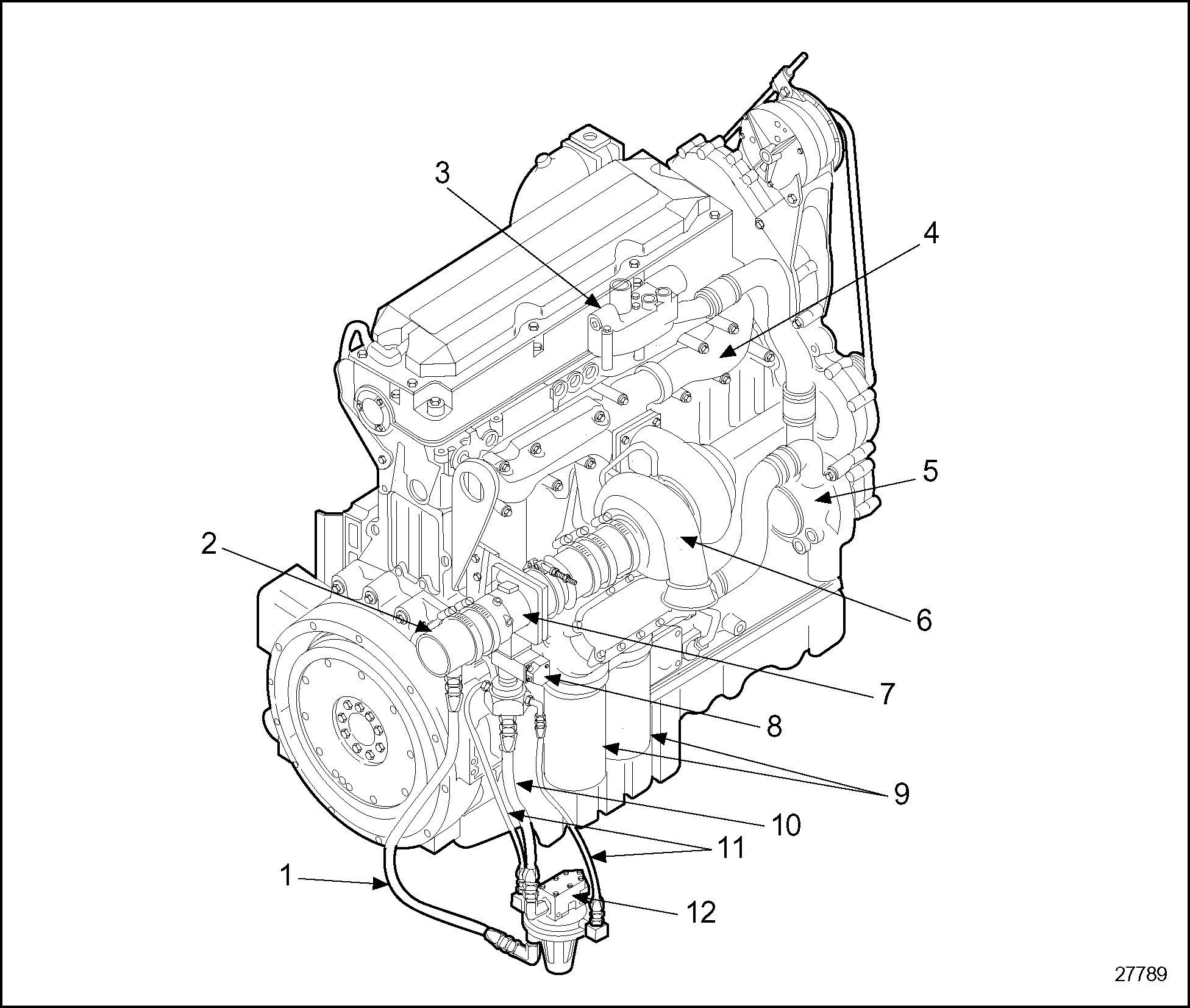
The fuel system uses computer calculations for both fuel flow and air flow, while maintaining a lean air - fuel mixture for low emissions and good fuel economy. Calculations are based on knowing the temperature of the air and fuel along with the temperature and pressure of the fuel and air mixture in the inlet manifold. The air temperature sensor is located in the air intake tube located in front of the gas mixer. The fuel temperature sensor is located in the gas mixer. An intake manifold pressure sensor is located in the intake manifold. See Figure "Low Pressure Fuel System (Series 60G Engine)" .

|
1. Air Balance Hose |
7. Fuel Mixer Assembly |
|
2. Air Inlet Tube |
8. Pulse Width Modulated Stepper Motor Valve (PSV) |
|
3. Thermostat Housing |
9. Lube Oil Filters |
|
4. Exhaust Manifold |
10. Fuel Supply Hose |
|
5. Fresh Water Pump |
11. Fuel Balance Hoses |
|
6. Turbocharger |
12. Low Pressure Regulator |
Figure 1. Low Pressure Fuel System (Series 60G Engine)
|
EXPLOSION |
|
To avoid injury from an explosion of natural gas, the following precautions must be taken:
|
|
EXPLOSION |
|
To avoid injury from the explosion of natural gas, the engine must be kept in a well ventilated area away from open flames, sparks, and electrical resistance (heating) coils. |
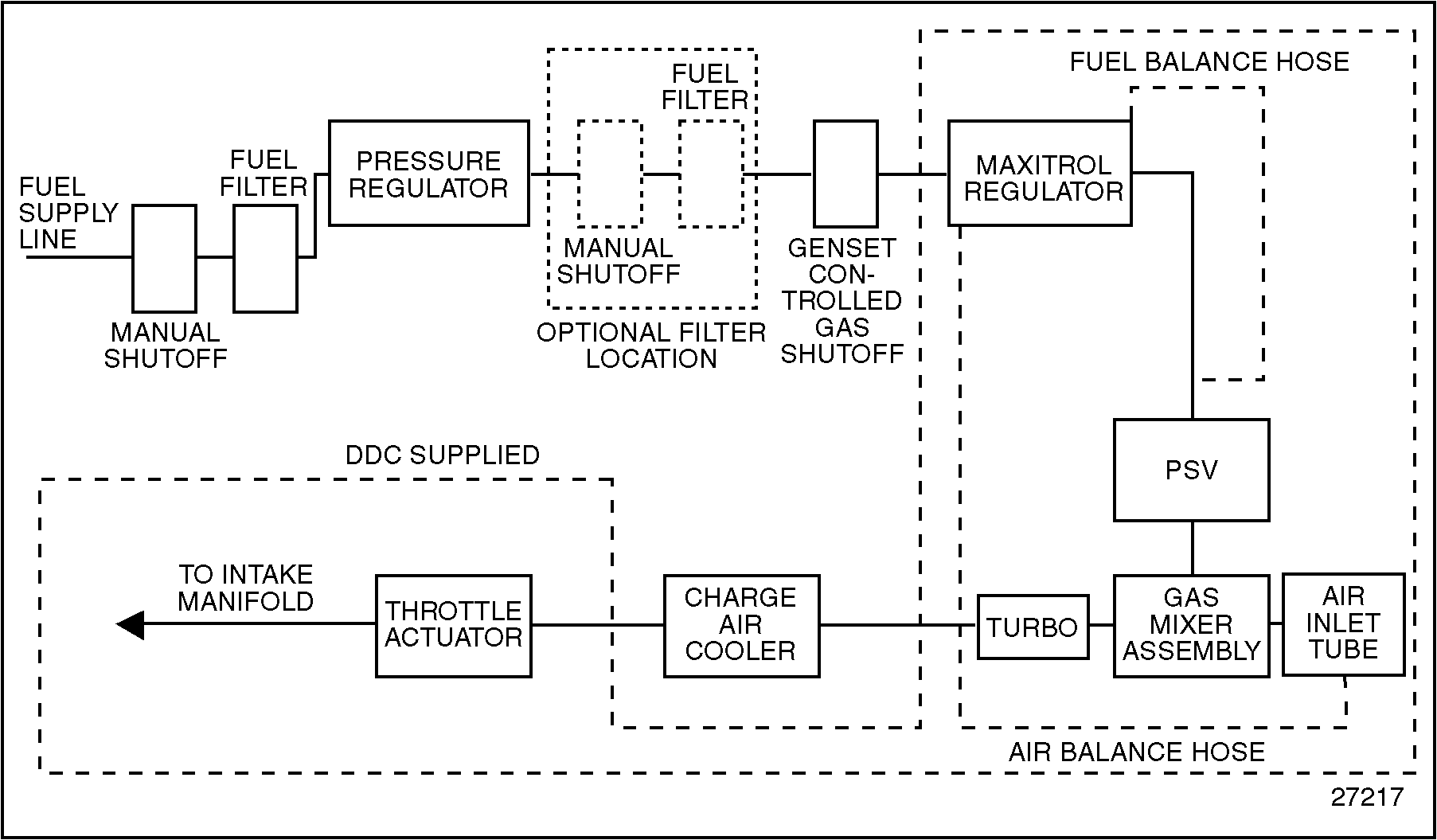
The Series 60 natural gas engine low pressure fuel system consists of a venturi type fuel mixer, Pulsewidth Modulated Stepper Motor Valve (PSV), and low pressure regulator. It is referred to as a "demand" system in that the venturi mixer generates a suction at the regulator outlet. The regulator adjusts its outlet pressure in response to the demand (suction) of the venturi resulting in an increase of fuel flow. The opposite is true for conditions requiring a decrease in fuel flow. See Figure "Low Pressure Natural Gas Fuel System (Series 60G Engine)" .

Figure 2. Low Pressure Natural Gas Fuel System (Series 60G Engine)
Fuel supply is routed to the inlet side of the low pressure regulator at a pressure of 1-5 kPa (5-20 in. H2 O). The low pressure regulator is a balanced regulator and as such, reduces this pressure to a level approximately equal to air inlet pressure.
Regulated fuel is routed from the low pressure regulator to the PSV. The PSV is fully controlled by DDEC III/IV and is used to bias fuel flow, rich or lean, based on a predetermined engine calibration.
Fuel from the PSV enters the venturi mixer where it is drawn into and mixed with the airstream ahead of the turbocharger compressor inlet, charge air cooler, throttle and intake manifold.
| Series 60 Service Manual - 6SE483 |
| Generated on 10-13-2008 |