Section 2.3
Injector Pump
The fuel injection system is responsible for supplying the diesel engine with fuel. To do so, the injection pump generates the pressure required for fuel injection. The fuel under pressure is forced through the high-pressure fuel-injection tubing to the injection nozzle which then injects it into the combustion chamber. The fuel injection system includes the following components and assemblies (see Figure "Injection Pump Parts Location" ):
- Fuel tank
- Fuel filter
- Transfer pump
- Injection nozzles
- High pressure fuel injection lines
- Electronic control unit
- Injection pump

|
1.Flange Nut |
9.Washers |
|
2.Injector Pump Gear |
10.Valve Kit |
|
3.Gasket |
11.Spill Adaptor |
|
4.Stud |
12.Nut |
|
5.Injection Pump |
13.Flange Nut |
|
6.Washer |
14.Washer |
|
7.Banjo Connector |
15.Key |
|
8.Banjo Bolt |
|
Figure 1. Injection Pump Parts Location
The combustion process in the diesel engine depends to a large degree upon the quantity of fuel which is injected and upon the method of introducing this fuel to the combustion chamber.
The most important criteria in this respect are the fuel-injection timing and the duration of injection, the fuel's distribution in the combustion chamber, the moment in time when combustion starts, the amount of fuel metered to the engine per degree crankshaft, and the total injected fuel quantity in accordance with the engine loading. The optimum interplay of all these parameters is decisive for the faultless functioning of the diesel engine.
Section 2.3.1
Repair or Replacement of Injector Pump
To determine if replacement of the injection pump is necessary, perform the following procedure. See Figure "Flowchart for Replacement of the Injection Pump" .

Figure 2. Flowchart for Replacement of the Injection Pump
Section 2.3.2
Removal of Injector Pump
Remove the fuel injection pump as follows:
- Remove access plug.
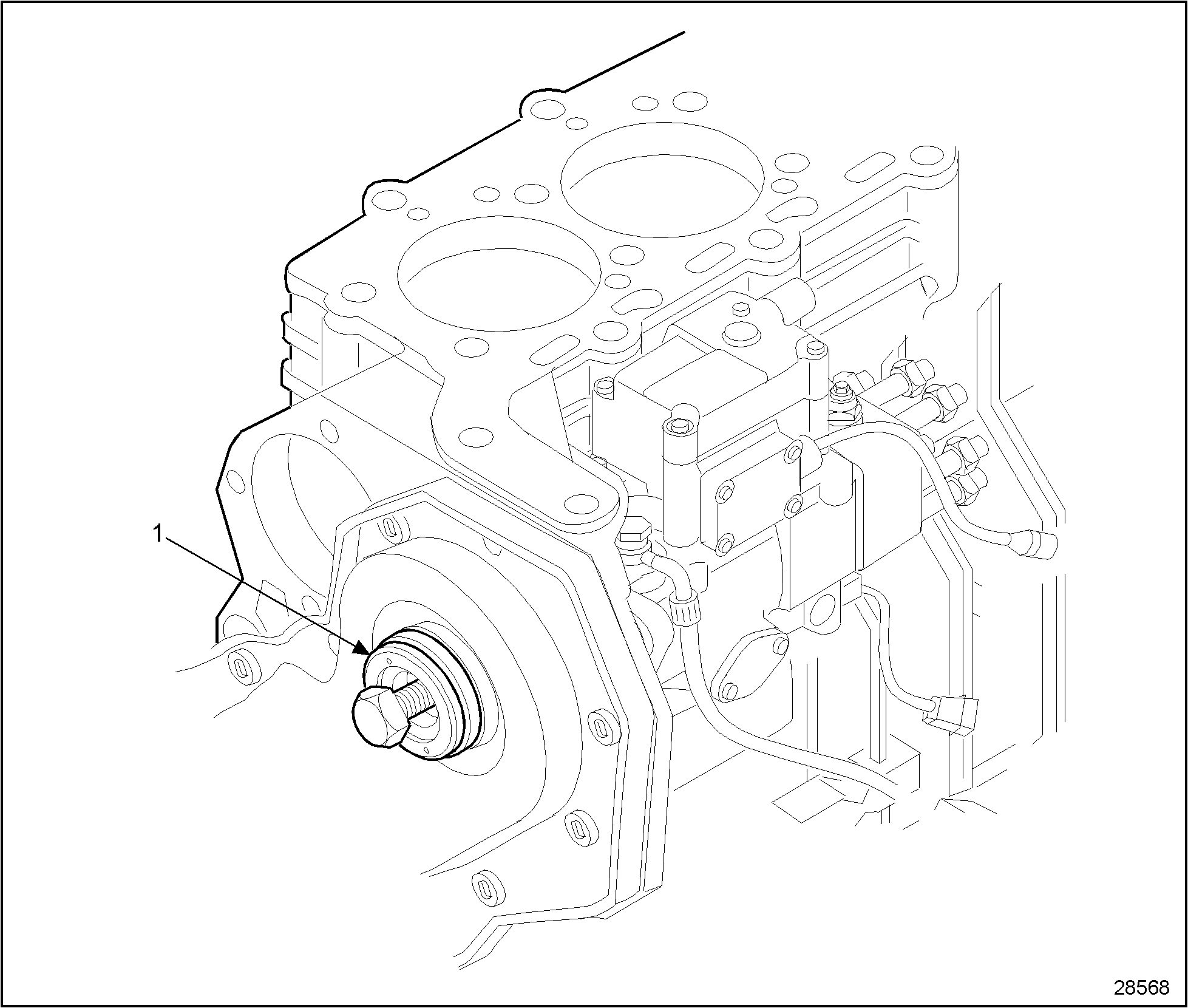
- Turn the crankshaft to position the number one piston at top-dead-center (TDC). Then rotate engine counterclockwise approximately 155 until the injection pump keyway is at the 11 o'clock position. See Figure
"Injection Pump Keyway"
.
Note: The injection pump gear has two key slots. The slot with the shaft key should be at the 11:00 o'clock position.

1.Keyway Location
Figure 3. Injection Pump Keyway
- Remove the high pressure fuel lines. Refer to "2.4.2 Removal of High Pressure Fuel Lines" .
- Disconnect all electrical harnesses from the injection pump.
- Remove fuel supply lines and return lines from the injection pump.
- Remove the injection pump gear retaining nuts and lockwashers.
- Install J 42671 (injection pump puller) to the front cover. See Figure
"Installing J 42671 Injection Puller Tool"
.

Figure 4. Installing J 42671 Injection Puller Tool
- Remove three injection pump mounting nuts and flat washers.
- Tighten center screw of J 42671 tool and remove the injection pump from the gear assembly.
- Remove the injection pump and J 42671.
Note: J 42671 inner and outer ring must remain on the front cover to maintain correct gear train timing.
Section 2.3.2.1
Inspection of Injector Pump
Inspect the injection pump as follows:
- Visually check the injection pump mounting flanges for cracks.
- If the injection pump mounting flanges are cracked, replace the component. Refer to "2.3.3 Installation of Injector Pump" .
- If the injection pump mounting flanges are not cracked, proceed with step 2 of inspection.
- Visually check the injection pump gear for burrs or damaged gear teeth.
- If the injection pump gear is burred or the gear teeth are damaged, replace the gear. Refer to "2.3.3 Installation of Injector Pump" .
- If the injection pump gear is not burred or the gear teeth are not damaged, proceed with step 3 of inspection.
- Visually check the injection pump shaft for burrs.
- If the injection pump shaft is burred, repair using emery cloth to remove burrs. Refer to "2.3.3 Installation of Injector Pump" .
- If the injection pump shaft is not burred, reuse the component. Refer to "2.3.3 Installation of Injector Pump" .
Section 2.3.3
Installation of Injector Pump
Install the injection pump as follows:
- Loosely install the injection pump and secure using the three injector pump mounting nuts and flat washers.
- Remove J 42671 and install the gear retaining nut and lockwasher. Torque nut to 85-87 N · m (63-64 lb · ft).
- Connect fuel supply lines and return lines to the injector pump.
- Connect all electrical harness to the injector pump.
- Install the high pressure fuel lines. Refer to "2.4.3 Installation of High Pressure Fuel Lines" .
- Install access plug.
- Perform an injection pump timing. Refer to "2.3.3.1 Timing of Injection Pump" .
- Run engine to verify repairs.
Section 2.3.3.1
Timing of Injection Pump
Perform an injection pump timing as follows:
- Remove the central screw from the rear of the injection pump.
- Install J 42670 and a dial gage to the injection pump. See Figure
"Injection Pump Timing Gage"
.

1.Injection Pump
2.Dial Gage and Adaptor
Figure 5. Injection Pump Timing Gage
- Slightly rotate the engine in a clockwise direction until the engine is at number one top-dead-center (TDC) and then in a counterclockwise direction until the dial indicator stops moving (20-255 before top-dead-center).
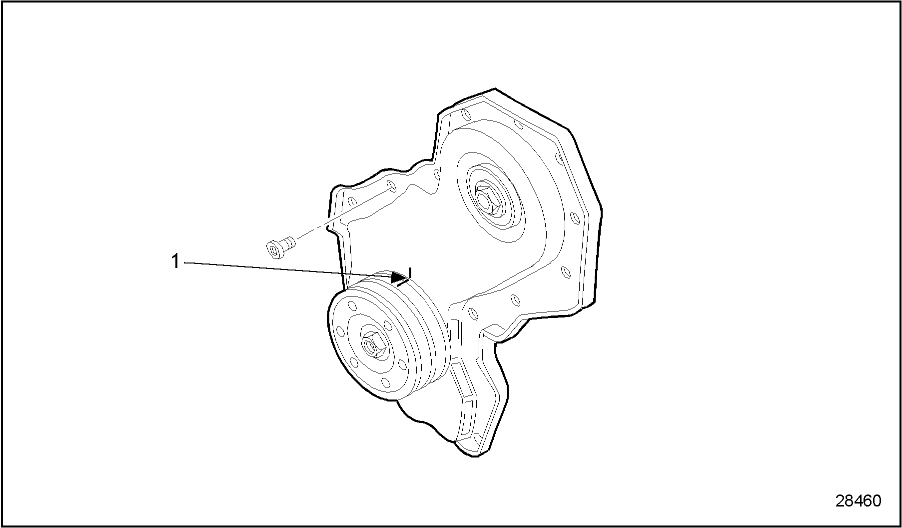
- Set the dial gage to zero and rotate the crankshaft clockwise until the marks on the pulley and the front cover are aligned. See Figure
"Pulley and Front Cover Alignment"
.

1.Timing Mark Location
Figure 6. Pulley and Front Cover Alignment
- Check that the dial gage reading is at 0.70 mm (0.028 in.). If the reading is different, adjust the pump position slightly by rotating it to the left or right until the required reading is obtained.
- Remove J 42670 and gage.
- Reinstall center plug.
- Run engine to verify repair.
| Series 638 Service Manual - 6SE648 |
| Generated on 10-13-2008 |