Section 4.1
Cooling System Overview
The cooling system consists of the following components (see Figure "Cooling System Operation" ):
- Water pump
- Pressure control cap
- Thermostat
- Engine coolant fan
- Coolant filter and conditioner
- Radiator

|
1. Oil Cooler Housing |
5. Water Bypass Tube |
|
2. Thermostat Housing |
6. Water Pump |
|
3. Vent Line Outlet |
7. Oil Pan |
|
4. Water Outlet (To Radiator) |
|
Figure 1. Cooling System Operation
An OEM supplied radiator along with a factory installed thermo-modulated fan are used to effectively dissipate the heat generated by the engine. A centrifugal-type water pump is used to circulate the engine coolant.
Two full blocking-type thermostats are used in the water outlet passage to control the flow of coolant, providing fast engine warm-up and regulating coolant temperature. Listed in Table "Series 50 Air System, Fuel System, and Cooling System Parameters" are the normal cooling system operational parameters.
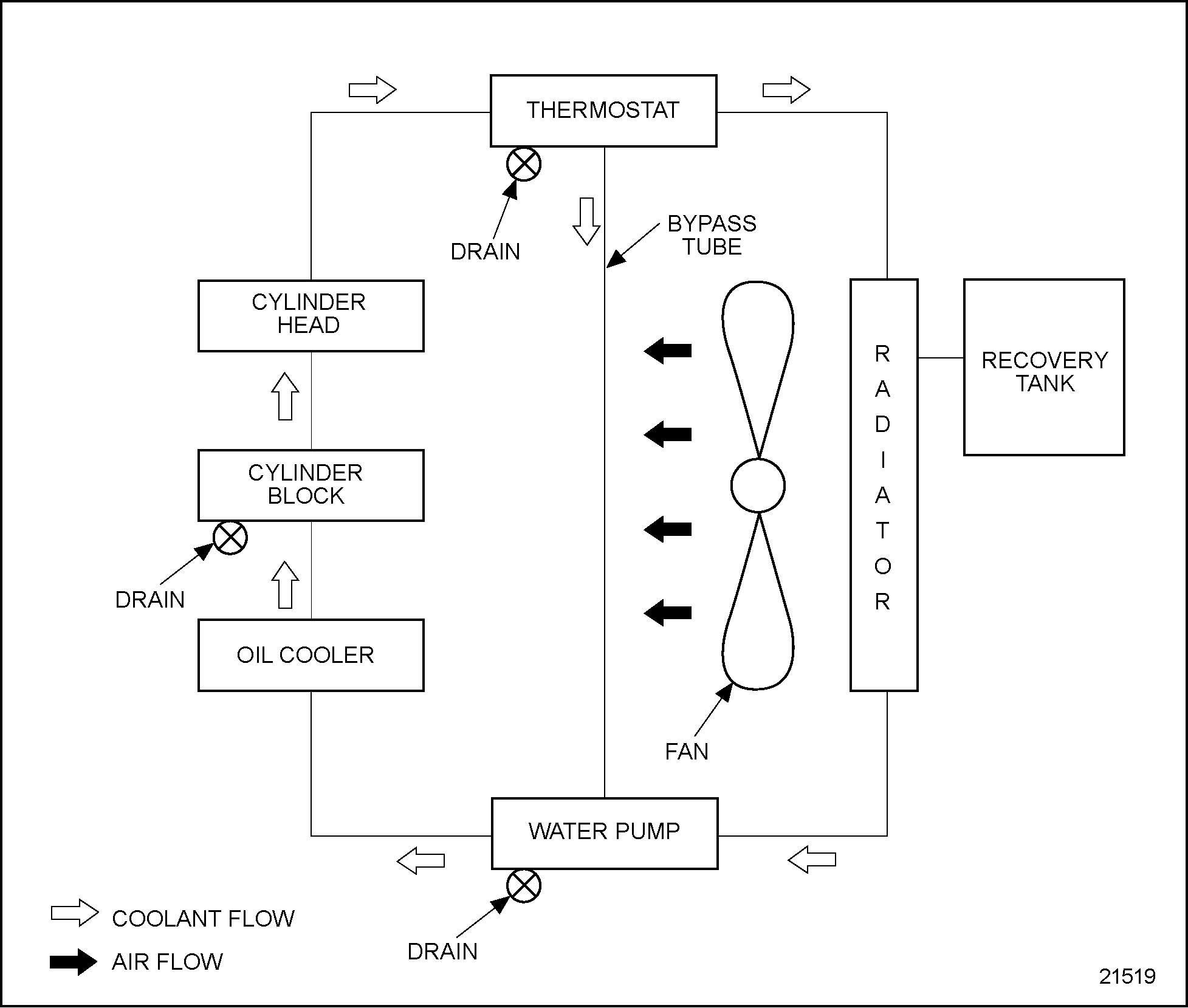
The pressurized engine coolant is drawn from the lower portion of the radiator by the water pump and is forced through the oil cooler and into the cylinder block. See Figure "Coolant Flow Schematic" .

Figure 2. Coolant Flow Schematic
When the engine is at normal operating temperature, the coolant passes from the cylinder block up through the cylinder head, through the thermostat housing and into the upper portion of the radiator. The coolant then passes through a series of tubes where the coolant temperature is lowered by the airflow created by the revolving fan and the motion of the vehicle.
Upon starting a cold engine or when the coolant is below operating temperature, the closed thermostats direct coolant flow from the thermostat housing through the bypass tube to the water pump. Coolant is recirculated through the engine to aid engine warm-up. When the thermostat opening temperature is reached, coolant flow is divided between the radiator inlet and the bypass tube. When the thermostats are completely open, all of the coolant flow is to the radiator inlet.
The function of the engine coolant is to absorb the heat, developed as a result of the combustion process in the cylinders, from component parts such as the valves and pistons which are surrounded by water jackets. In addition, the heat absorbed by the oil is also removed by the engine coolant in the oil-to-water oil cooler. Refer to "5.4 Coolant" for coolant recommendations.
A pressurized cooling system permits higher temperature operation than a non-pressurized system. It is essential that the cooling system is kept clean and leak-free, that the filler cap and pressure relief mechanisms are properly installed and operate correctly, and that the coolant level is properly maintained.
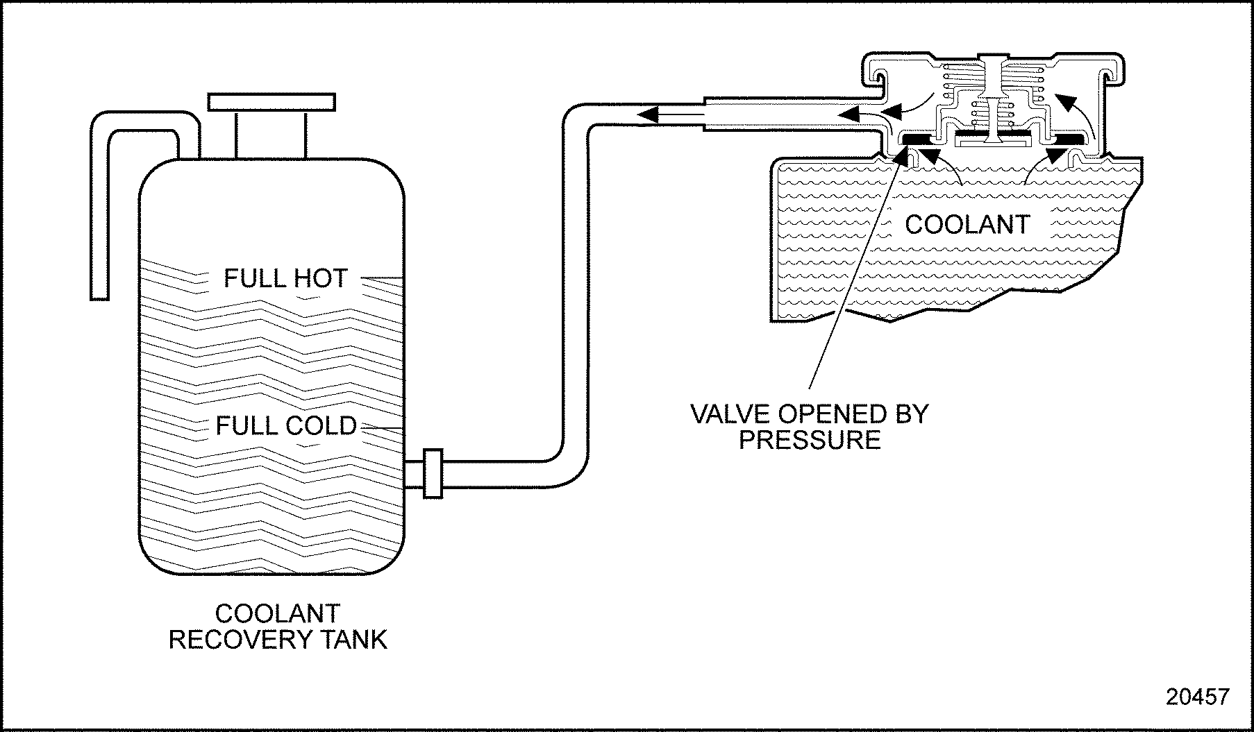
As the engine temperature increases, the coolant and air in the system starts to expand and build pressure. The valve in the radiator pressure cap unseats and allows the coolant to flow into the coolant recovery tank. See Figure "Coolant Expansion" .

Figure 3. Coolant Expansion
When the engine starts to cool down, the air and coolant contract, causing a void and creating a vacuum in the system. The vacuum unseats another valve in the radiator pressure cap, allowing the coolant to flow back into the expansion tank or radiator. See Figure "Coolant Recovery" .

Figure 4. Coolant Recovery
| Series 50 Service Manual - 6SE50 |
| Generated on 10-13-2008 |