Section 6.3
SID 21, FMI 1, Flash Code 42, Too Few SRS (Missing SRS)
The Synchronous Reference Sensor (SRS) indicates the position of No. 1 (front) cylinder. See Figure "The TRS and SRS" .

Figure 1. The TRS and SRS
SID 21, FMI 1, Flash Code 42 indicates that the ECM has not detected the required SRS pulses.
Section 6.3.1
Troubleshooting SID 21, FMI 1, Flash Code 42
Troubleshoot as follows:
NOTICE: |
|
To avoid damage to the harness and connectors when disconnecting harness connectors, ensure the pulling force is applied to the connectors and not to the wires extending from the connectors. |
- Check wire 111 [light blue, SRS (+)] for continuity at cavity S-2 in the Engine Sensor Harness (ESH) 30–pin connector (see Figure
"Engine Sensor Harness 30–pin Connector"
) and pin B in the SRS connector (see Figure
"The TRS and SRS"
). Repair or replace wire if path is open.
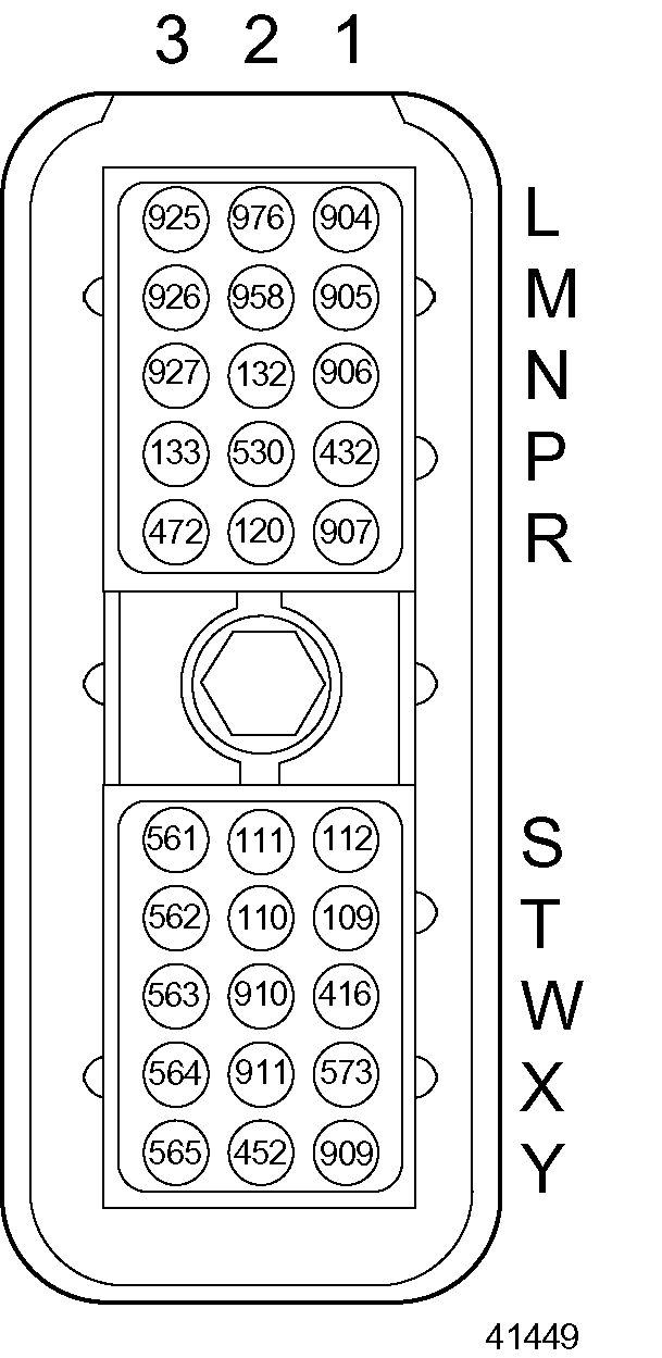
Figure 2. Engine Sensor Harness 30–pin Connector
- If the code is still active, go to step 2.
- If the code is no longer active, refer to "6.3.2 Verification" .
- Check wire 111 [light blue, SRS (+)] for short to ground at cavity S-2 in the ESH 30–pin connector (see Figure
"Engine Sensor Harness 30–pin Connector"
) and pin B in the SRS connector (see Figure
"The TRS and SRS"
). If there is a short, repair or replace the wire.
- If the code is still active, go to step 3.
- If the code is no longer active, refer to "6.3.2 Verification" .
- Check wire 111 [light blue, SRS (+)] for short to wire 416 (gray, 5 VDC sensor supply) at cavities S-2 (wire 111) and W-1 (wire 416) in the ESH 30–pin connector (see Figure
"Engine Sensor Harness 30–pin Connector"
) and pin B in the SRS connector (see Figure
"The TRS and SRS"
). If there is a short, repair or replace the wire(s).
- If the code is still active, go to step 4.
- If the code is no longer active, refer to "6.3.2 Verification" .
- Check wire 112 [white, SRS (-)] for continuity at cavity S-1 in the ESH 30–pin connector (see Figure
"Engine Sensor Harness 30–pin Connector"
) and pin A in the SRS connector (see Figure
"The TRS and SRS"
). Repair or replace wire if path is open.
- If the code is still active, go to step 5.
- If the code is no longer active, refer to "6.3.2 Verification" .
- Check wire 112 [white, SRS (-)] for short to ground at cavity S-1 in the ESH 30–pin connector (see Figure
"Engine Sensor Harness 30–pin Connector"
) and pin A in the SRS connector (see Figure
"The TRS and SRS"
). If there is a short, repair or replace the wire.
- If the code is still active, go to step 6.
- If the code is no longer active, refer to "6.3.2 Verification" .
- Check wire 112 [white, SRS (-)] for short to wire 416 (gray, 5 VDC sensor supply) at cavities S-1 (wire 112) and W-1 (wire 416) in the ESH 30–pin connector (see Figure
"Engine Sensor Harness 30–pin Connector"
) and pin A in the SRS connector (see Figure
"The TRS and SRS"
). If there is a short, repair or replace the wire(s).
- If the code is still active, call Detroit Diesel Technical Service.
- If the code is no longer active, refer to "6.3.2 Verification" .
Section 6.3.2
Verification
Verify that troubleshooting was successful :
- Check the DDR to see if SID 21, FMI 1, Flash Code 42 is still active.
- If the code is still active, go to step 2.
- If the code is not active, troubleshooting is complete.
- If code is still active, call Detroit Diesel Technical Service.
| Series 50G and 60G Troubleshooting Guide - 6SE482 |
| Generated on 10-13-2008 |
Problema com motor Detroit série 60 código 636 motor não pega?