Section 6.3
Intake Manifold
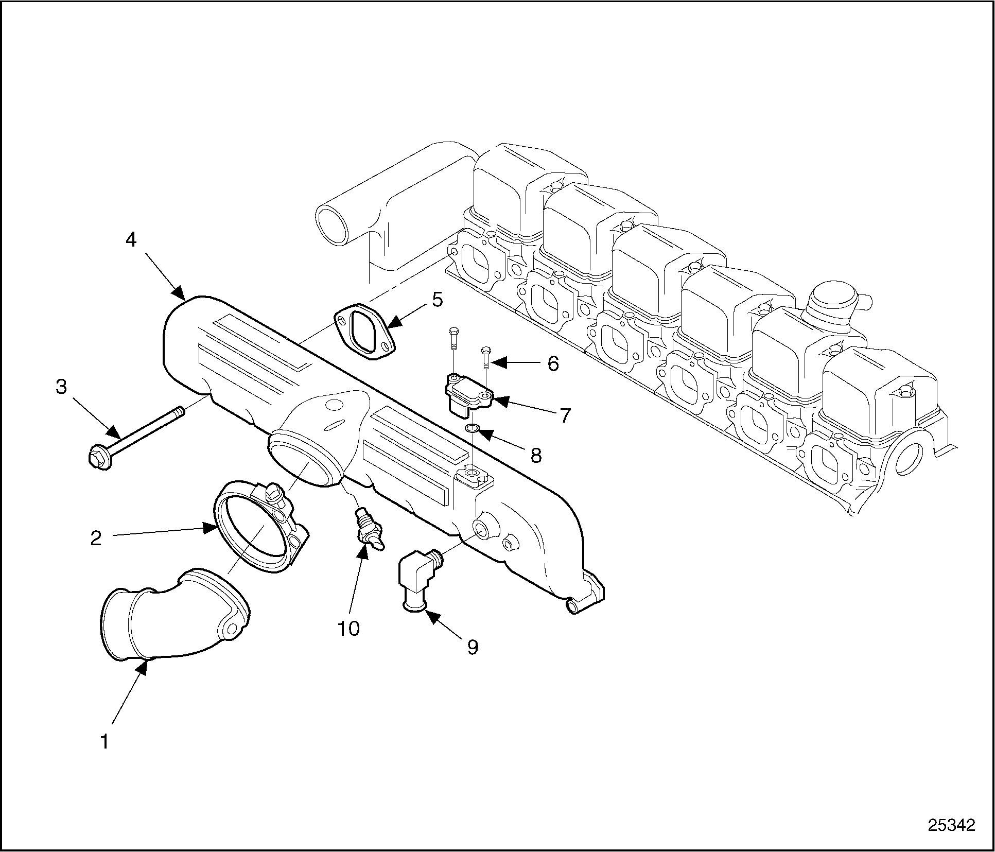
The intake charged air is routed to the individual cylinders by an intake manifold bolted to the cylinder head with twelve mounting bolts. The mating surfaces of the intake manifold and cylinder heads are machined. The intake manifold is sealed to the cylinder heads with six single port gaskets. If the manifold is removed, new gaskets must be installed to maintain seal under higher boost pressure. A turbo-boost pressure sensor is mounted to the side of the intake manifold with two bolts. An O-ring seals the boost sensor where it enters a hole in the manifold. An air temperature sensor is located on the bottom center of the manifold. See Figure "Intake Manifold" .

|
1.Air Inlet Elbow |
2.Air Intake Manifold |
Figure 1. Intake Manifold
Section 6.3.1
Repair or Replacement of Intake Manifold
Repair of the intake manifold is not authorized by Detroit Diesel.
To determine if repair or replacement of the intake manifold is necessary, perform the following procedure. See Figure "Repair or Replacement of Intake Manifold Flowchart" .

Figure 2. Repair or Replacement of Intake Manifold Flowchart
Section 6.3.2
Removal of Intake Manifold
Clean the mounting area between intake manifold and cylinder head to prevent any foreign material from falling into the cylinder head intake ports.
Remove the intake manifold as follows:
- Disconnect the air inlet elbow clamp from the intake manifold. See Figure
"Air Inlet Elbow and Intake Manifold Removal"
.

1.Air Inlet Elbow
6.TBS Bolts (2)
2.Clamp
7.Turbo Boost Sensor (TBS)
3.Intake Manifold Mounting Bolts (12)
8.O-ring Seal
4.Intake Manifold
9.Air Compressor Elbow
5.Intake Manifold Gaskets (6)
10.Air Temperature Sensor
Figure 3. Air Inlet Elbow and Intake Manifold Removal
- Remove the air temperature sensor from the intake manifold. See Figure "Air Inlet Elbow and Intake Manifold Removal" .
- Remove the two screws securing the turbo boost sensor to the intake manifold.
- Disconnect the air compressor hose from the brass elbow on the intake manifold.
- Remove the brass air compressor hose elbow from the intake manifold.
- Remove the twelve mounting bolts securing the intake manifold to the cylinder heads.
- Remove the intake manifold and six intake manifold gaskets. Discard the mounting gaskets.
- Remove all traces of the old gasket from each cylinder head.
Section 6.3.2.1
Inspection of Intake Manifold
Inspect the intake manifold as follows:
- Inspect the intake manifold for cracks, stripped mounting bolt threads, or other damage. If any of these conditions is detected, replace the intake manifold.
Section 6.3.3
Installation of Intake Manifold
Install the intake manifold as follows:
- Install two mounting bolts and new washers through each end of the intake manifold. See Figure
"Air Inlet Elbow and Intake Manifold Installation"
.

1.Air Inlet Elbow
6.Turbo Boost Sensor Bolt (2)
2.Clamp
7.Turbo Boost Sensor
3.Intake Manifold Mounting Bolts (12)
8.O-ring
4.Intake Manifold
9.Air Compressor Elbow
5.Intake Manifold Gaskets (6)
10.Air Temperature Sensor
Figure 4. Air Inlet Elbow and Intake Manifold Installation
- Install new mounting gaskets, using mounting bolts to hold the intake manifold gaskets in position.
- Position the intake manifold against the cylinder heads and tighten the mounting bolts finger-tight.
- Position the remaining intake manifold gaskets between the intake manifold and cylinder head. Use the mounting bolts to secure the gaskets in position
- Tighten the mounting bolts finger-tight.
Note: Insure all six mounting gaskets are properly positioned between the intake manifold and cylinder head intake ports.
- Tighten the bolts to 25 N · m (19 lb · ft) torque, starting with the two end cylinders and working toward the center bolts.
- Install the air compressor hose fitting.
- Reconnect the air compressor hose to the intake manifold brass fitting.
- Install the air inlet temperature sensor.
- Install the two turbo boost sensor screws. Tighten them to 2.4-2.9 N · m (21-26 lb · in.) torque.
- Install the air inlet elbow clamp to the intake manifold.
- Tighten the elbow clamp to 15 N · m (11 lb · ft).
| Series 55 Service Manual - 6SE55 |
| Generated on 10-13-2008 |