Section 1.18
Piston, Piston Ring, and Connecting Rod
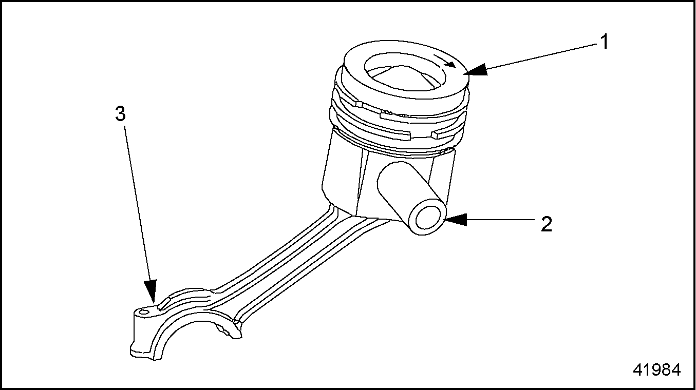
The pistons are made of aluminum alloy with ring carriers and a shallow combustion chamber recess. The pistons are cooled by oil spray nozzles. See Figure "Piston Assembly (exploded view)" for an exploded view of the piston and connecting rod assembly.

|
1. Piston and Rings |
4. Connecting Rod |
7. Bearing Shell |
|
2. Wrist Pin |
5. Bearing Cap |
|
|
3. Snap Ring |
6. Connecting Rod Stretch Bolt |
Figure 1. Piston Assembly (exploded view)
Section 1.18.1
Piston Removal
Remove the piston assembly as follows:
- Remove each cylinder head, as required. Refer to "1.2.1 Cylinder Head Removal"
.
Note: The MBE 4000 engine has individual heads for each cylinder. To remove one piston, do these procedures step by step. To remove all the pistons, repeat each step in these instructions, as applicable, for all six pistons.
- Remove the oil pan.
NOTICE:
Do not damage the piston travel surface of the cylinder.
- Using a plastic scraping tool, carefully scrape off any combustion residues from the combustion area in the cylinder in order to avoid damage to the piston rings when the piston is removed.
- Install the engine barring tool (J–46392) . Refer to "1.16.1 Engine Barring Tool Installation" .
- Be sure the connecting rods and the bearing caps are marked so that they can be matched for installation. See Figure
"Checking Rod and Bearing Cap Markings"
.

1. Bearing Cap
2. Connecting Rod
Figure 2. Checking Rod and Bearing Cap Markings
- Remove and inspect the oil spray nozzles. See Figure
"Location of Oil Spray Nozzle"
. Replace them if damaged.

1. Oil Spray Nozzle
2. Cylinder Liner
Figure 3. Location of Oil Spray Nozzle
- Remove the connecting rod stretch bolts and bearing cap. See Figure
"Removing the Bearing Caps"
.

Figure 4. Removing the Bearing Caps
Note: If the bearing shell halves are removed from the rods and caps, be sure to mark them so they can be matched for installation.
- Remove the bearing shell halves from the bearing cap and connecting rod.
- Push the piston and connecting rod out of the cylinder, and remove them both from the cylinder block.
- Secure the connecting rod in a vise with protective jaws.
NOTICE:
Be sure the vise jaws are adequately lined to prevent the rod surface from being nicked or marred in any way. Such surface damage could lead to later rod cracking or breaking.
- Remove the piston rings from the piston. Refer to "1.18.3 Piston Ring Replacement" .
- Remove the wrist-pin snap rings. Push the wrist pin out and remove the piston from the connecting rod.
Section 1.18.1.1
Piston Inspection
Inspect the piston as follows:
- Remove the piston. Refer to "1.18.1 Piston Removal" .
- Check the diameter of the wrist pin and the wrist pin bore. See Figure
"Piston Assembly (exploded view)"
. Specifications are listed in Table
"Piston Inspection Specifications"
.
1. Piston and Rings
4. Connecting Rod
7. Bearing Shell
2. Wrist Pin
5. Bearing Cap
3. Snap Ring
6. Connecting Rod Stretch Bolt
Figure 5. Piston Assembly (exploded view)
Description
Dimensions: mm (in.)
Piston Compression Height
79.50-79.55 (3.130-3.132)
Wrist Pin Bore Diameter
52.03-52.04 (2.0484-2.0488)
Wrist Pin Diameter
51.992-51.998 (2.0469-2.0472)
Table 7. Piston Inspection Specifications - Inspect the cylinder liner and piston for damage and signs of wear. Replace any piston with damage to the snap ring grooves, cracks in the piston wall, or signs of seizing and/or erosion.
- Check the tolerance code on the piston and compare it to the tolerance code on the cylinder liner. See Figure
"Tolerance Codes"
.

1. Piston
2. Cylinder Liner
Figure 6. Tolerance Codes
- Check the condition of the piston rings. Replace any worn, damaged, or chipped rings. Refer to "1.18.3 Piston Ring Replacement" .
- Check the connecting rod for any unusual condition. Refer to "1.18.1.2 Connecting Rod End Play Measurement" .
- Measure the diameters of the bearing shell bore and crankshaft journals. Refer to "1.18.1.3 Connecting Rod Radial Play Measurement" for instructions.
- Check the length of the connecting rod stretch bolts. See Figure
"Measuring a Stretch Bolt"
. Replace any bolts that exceed the maximum length of 68.5 mm (2.70 in.).

1. Shank
Figure 7. Measuring a Stretch Bolt
Section 1.18.1.2
Connecting Rod End Play Measurement
Measure the connecting rod end play as follows:
- Remove the piston. Refer to "1.18.1 Piston Removal" .
- Inspect the connecting rod for blue discoloration (indicates bearing damage), scoring, notches, and cracks. If any of these conditions are found, replace the connecting rod.
- Measure the inside diameter of the bushing in the small bore of the connecting rod. Use a quick-release caliper (internal measurement, 40 to 60 mm), with a dial gauge and holder.
If the value exceeds 52.07 mm (2.050 in.), replace the connecting rod.

1. Dial Gauge
4. Connecting Rod
7. Stretch Bolt (2 qty.)
2. Dial Gauge Holder
5. Bearing Shell (2 halves)
3. Bushing
6. Bearing Cap
Figure 8. Measuring Inside Diameters in the Connecting Rod
Note: Checking the connecting rod for a twisted or bent condition in the next step requires machine shop equipment such as a caliper gauge with a round scale.
NOTICE:
Do not attempt to straighten the connecting rod. This could result in severe engine damage.
- Inspect the connecting rod for twisting and dimensional tolerance. see Figure
"Connecting Rod Measurements"
. If any value exceeds those listed in Table
"Connecting Rod Dimensional Tolerances"
, replace the connecting rod.

Figure 9. Connecting Rod Measurements
Description
Dimensions: mm (in.)
Length of Connecting Rod
255.970-256.030 (10.0775-10.0799)
Basic Bore Diameter for Connecting Rod Bearings
99.000-99.022 (3.8976-3.8985)
Maximum Permissible Out-of-Round in Bearing Bore
0.01 (0.0004)
Maximum Permissible Out-of-Round in Bushing Bore
0.01 (0.0004)
Maximum Difference in Axial Parallelism Between Bearing Bore and Bushing Inner Surface
0.030 (0.0012)
Width of Connecting Rod (at big end)
44.308-44.370 (1.744-1.7468)
Width of Connecting Rod Journal
44.5-44.6 (1.75-1.76)
Distance from Connecting Rod Center Line for Measuring Parallelism
50 (2)
Table 12. Connecting Rod Dimensional Tolerances- On each side of the connecting rod, measure the length of the connecting rod (Dimension A in see Figure "Connecting Rod Measurements" ): the distance from the center bearing bore (big-end bore) to the center of the bushing (small-end bore). The measurement must be within 255.970 to 256.030 mm (10.0775 to 10.0799 in.).
- Measure the difference in axial parallelism (Dimension B in see Figure "Connecting Rod Measurements" ) between the bearing bore and the inner surface of the bushing, at 50 mm (2 in.) from the connecting-rod centerline (Dimension C in see Figure "Connecting Rod Measurements" ). The maximum allowed difference is 0.030 mm (0.0012 in.).
- Measure the diameter of the connecting rod basic bore, with the bearing shells removed. The diameter of the basic bore must be between 99.000 to 99.022 mm (3.8976 to 3.8985 in.).
- Measure the maximum permissible out-of-round in the bearing bore, with the bearing shells removed. The maximum permissible is 0.01 mm (0.0004 in.).
- Calculate the connecting rod end play, or axial play, (fore-to-aft movement) on the crankshaft.
If the end play is less than 0.130 mm (0.0051 in.), or more than 0.292 mm (0.0115 in.), replace the connecting rod. Listed in Table "Connecting Rod Dimensional Tolerances" .
- For each bearing journal, note the width (thickness) of the bearing journal. Example: Wj = 1.8120 inches.
- For each connecting rod, note the width (thickness) of the rod. Example: Wr = 1.8050 inches.
- From the value for the journal width, subtract the value for the connecting rod width. This result is the end play. Example: Wj —Wr = 0.0070 inch.
- Remove the bolts and bearing cap when ready to install the piston.
- Install the piston. Refer to "1.18.2 Piston Installation" .
Section 1.18.1.3
Connecting Rod Radial Play Measurement
Measure the connecting rod radial play as follows:
- Remove the piston. Refer to "1.18.1 Piston Removal" .
- Using a chamois cloth, clean the bearing bores in both the connecting rod and the bearing cap.
- Install the two matched halves of the bearing shell, as marked on removal, into the connecting rod and into the bearing cap. Be sure the locking lugs on the bearing shells fit into the grooves in the rod and cap. See Figure
"Bearing Shell Replacement"
.

1. Connecting Rod
3. Bearing Cap
2. Bearing Shell (2 halves)
4. Connecting Rod Bolt
Figure 10. Bearing Shell Replacement
- Install the bearing cap on the connecting rod, pressing it on by hand. Be sure that the marks on the cap and rod match.
- Lubricate the threads and the contact surface of the head of each stretch bolt with a light coating of engine oil.
- Install the stretch bolts in the connecting rod, and tighten them alternately. Tighten each one in turn to the first stage and then go on to the next stage, listed in Table
"Tightening Stages, Connecting Rod Stretch Bolts"
.
Max. Shaft Length: mm (in.)
Tightening Stage
Torque Value: N·m ( lb·ft)
68.5 (2.70)
Stage 1
108 (80)
68.5 (2.70)
Stage 2
additional 90 degrees
Table 14. Tightening Stages, Connecting Rod Stretch Bolts - Using a micrometer, measure the bearing journal on the crankshaft in both the vertical and horizontal plane and note the measurements. See Figure
"Measuring the Bearing Journal"
to locate the measuring points and listed in Table
"Bearing Journal Specifications"
are the current repair stage specifications.

Figure 11. Measuring the Bearing Journal
Repair Stage: mm (in.)
Diameter: mm (in.)
Standard
93.980-94.000 (3.7000-3.7007)
Undersize - 0.1 (0.004)
93.880-93.900 (3.6960-3.6968)
Undersize - 0.25 (0.010)
93.730-93.750 (3.6901-3.6909)
Undersize - 0.50 (0.020)
93.480-93.500 (3.6803-3.6811)
Undersize - 0.75 (0.030)
93.230-93.250 (3.6705-3.6712)
Undersize - 1.00 (0.040)
92.980-93.000 (3.6606-3.6614)
Table 15. Bearing Journal Specifications- Measure the bearing journal in the vertical plane and note the reading.
- Measure the bearing journal in the horizontal plane and note the reading.
- Calculate the average (nominal) bearing-journal diameter from these two measurements, and determine the current repair stage listed in Table
"Bearing Bore Inside Diameter with Bearing Shells Installed"
.
Repair Stage: mm (in.)
Diameter: mm (in.)
Standard
94.054-94.096 (3.7029-3.7046)
Undersize - 0.10 (0.004)
93.954-93.996 (3.6990-3.7006)
Undersize - 0.25 (0.010)
93.804-93.846 (3.6931-3.6947)
Undersize - 0.50 (0.020)
93.554-93.596 (3.6832-3.6848)
Undersize - 0.75 (0.030)
93.304-93.346 (3.6734-3.6750)
Undersize - 1.00 (0.040)
93.054-93.096 (3.6635-3.6652)
Table 16. Bearing Bore Inside Diameter with Bearing Shells InstalledNOTICE:
Be sure the vise jaws in the next step are adequately lined to prevent the connecting rod surface from being nicked or marred in any way. Such surface damage could lead to later cracking or breaking of the rod.
- Place the connecting rod in a vise with protective jaws. To prevent the rod from twisting excessively, position the rod in the vise as close as possible to the big-end bore.
- Set the caliper (internal measurement 80 to 100 mm) to the nominal bearing-journal diameter calculated above. Use a 75 to 100 mm micrometer for the setting. Preload the setting 5 mm (0.2 in.). See Figure
"Setting the Caliper"
.

Figure 12. Setting the Caliper
- Using a quick-release caliper (internal measurement 80-120 mm), dial gauge, and holder, measure the inside diameter of the bearing bore (with the shells installed) at three points. Measure vertically and about 60 degrees each side of vertical. See Figure
"Measuring the Inside Diameter of the Bearing Shell"
to locate the measuring points, and find the current specifications listed in Table
"Bearing Bore Inside Diameter with Bearing Shells Installed"
.

1. Bolt
2. Bearing Cap
Figure 13. Measuring the Inside Diameter of the Bearing Shell
- Measure the bearing bore in the vertical dimension and note the reading.
- Mark off a point 60 degrees counterclockwise from vertical. Measure the bearing bore in this dimension and note the reading.
- Mark off a point 60 degrees clockwise from vertical. Measure the bearing bore in this dimension and note the reading.
- Calculate the average (nominal) bearing-journal diameter from these three measurements, and determine the current repair stage listed in Table
"Bearing Bore Inside Diameter with Bearing Shells Installed"
.
If any of the measurements are out of tolerance, replace the bearing shells.
Note: Connecting-rod bearings for all repair stages are delivered from the factory ready to install. Do not refinish them in any way.
Note: To obtain a correct value for connecting-rod radial play, the diameters of each bearing bore and its corresponding journal must belong to the same repair stage (both must be "standard," "undersize 0.1 mm," etc.).
- Calculate the connecting rod radial play (up-and-down movement) at the bearing journal. If the radial play is less than 0.054 mm (0.0021 in.), or more than 0.116 mm (0.0046 in.), replace the connecting rod. Listed in Table
"Connecting Rod Radial Play"
is the radial play.
Description
Dimensions: mm (in.)
Radial Play
0.054 - 0.116 (0.0021 - 0.0046)
Table 19. Connecting Rod Radial Play- For each connecting rod, note the average value for the bearing bore diameter, as calculated. Example: Ds = 3.5421 inches.
- For each bearing journal, note the average value for the bearing journal diameter, as calculated. Example: Dj = 3.5391 inches.
- From the value for the bearing bore diameter, subtract the value for the bearing journal diameter. This result is the radial play. Example: Ds
—Dj
= 0.0030 inch.
Note: In the above example, both measurements belonged to repair stage "undersize 0.1 mm."
- Remove the bearing cap from the connecting rod.
- Install the piston. Refer to "1.18.2 Piston Installation" .
Section 1.18.2
Piston Installation
Install the piston assembly as follows:
- Position the connecting rod in the piston so that the longer end side is on the unit pump side.
- Install the wrist pin in the piston. See Figure
"Installing the Wrist Pin"
.
1. Piston
2. Wrist Pin
Figure 14. Installing the Wrist Pin
- Lubricate the wrist pin with a light coating of clean engine oil.
- Insert the wrist pin into the wrist pin bore.
- Secure the wrist pin with the two snap rings.
- Install the piston rings on the piston. See Figure
"Ring Gaps Offset 120 Degrees"
. Refer to "1.18.3 Piston Ring Replacement"
.

1. Piston
Figure 15. Ring Gaps Offset 120 Degrees
- Lubricate the piston with a light coating of clean engine oil.
- Install each piston ring in the appropriate groove on the piston.
- Offset the ring gaps alternately by 120 degrees.
- Position a ring compressor loosely over the piston. Tighten the ring compressor on the piston.
NOTICE:
The half of the bearing shell installed in the connecting rod (rod half) has a specially-treated friction surface that allows it to bear higher loads. It cannot be interchanged (swapped) with the other half of the bearing shell installed in the bearing cap (cap half)..
- Install the rod half of the bearing shell in the connecting rod, as marked on removal. See Figure
"Installing the Bearing Shells"
.

1. Connecting Rod
2. Bearing Shells
3. Bearing Cap
Figure 16. Installing the Bearing Shells
- Be sure that the locking lug in the bearing shell is fully seated in the groove of the rod.
- Lubricate the bearing surface with a light coating of clean engine oil.
- Lubricate the cylinder liners with a light coating of clean engine oil.
NOTICE:
Be careful not to scratch the crankshaft journals with the connecting rod. This can lead to premature wear of the crankshaft.
-
Push the piston into the cylinder until the rod bearing rests on the crankshaft journal. See Figure
"Installing a Piston"
.

1. Ring Compressor
2. Piston
3. Cylinder Block
Figure 17. Installing a Piston
- Install the cap half of the bearing shell in the bearing cap, as marked on removal. See Figure
"Installing the Bearing Shells"
.
- Be sure that the locking lug in the bearing shell is fully seated in the groove of the cap.
- Lubricate the bearing surface with a light coating of clean engine oil.
- Measure the connecting rod stretch bolts. Replace any bolts that exceed the maximum length of 68.5 mm (2.70 in.). See Figure
"Measuring a Stretch Bolt"
. Lubricate the stretch bolt threads with a light coating of engine oil.
1. Shank
Figure 18. Measuring a Stretch Bolt
- Install the bearing cap on the connecting rod and hand-tighten the stretch bolts. Be sure that the marks on the cap and the rod match. See Figure "Checking Rod and Bearing Cap Markings" .
- Tighten the M16 x 1.5 connecting rod stretch bolts alternately. Tighten each one in turn to the first stage and then go on to the next stage. Listed in Table
"Tightening Stages, Connecting Rod Bolts"
.
Max. Shaft Length: mm (in.)
Tightening Stage
Torque Value: N·m (lb-ft)
68.5 (2.70)
Stage 1
100-115 (74-85)
Stage 2
additional 90-100°
Table 27. Tightening Stages, Connecting Rod Bolts - Check the connecting rod end play (axial play). Refer to "1.18.1.2 Connecting Rod End Play Measurement" .
- Rotate the crankshaft to make sure it turns freely.
Note: If it is necessary to turn the crankshaft and the flywheel has been removed, install the flywheel guide pins in the crankshaft gear.
- Using a dial gauge and holder, measure the piston projection relative to crankcase top dead center at all the pistons. See Figure
"Piston Projection at Top Dead Center (TDC)"
.

1. Piston
2. Cylinder Liner
Figure 19. Piston Projection at Top Dead Center (TDC)
- If the piston projection dimensions are not between 0.244 and 0.715 mm (0.0096 and 0.0281 in.), replace the piston. Listed in Table
"Piston Projection Specifications"
.
Description
Specification: mm (in.)
Piston Projection (at TDC)
0.244 – 0.715 (0.0096 – 0.0281)
Table 29. Piston Projection Specifications - Remove the engine barring tool (J–46392)
. Refer to "1.16.2 Engine Barring Tool Removal"
.
NOTICE:
Be careful not to damage the oil spray nozzles. Damaged oil spray nozzles could result in a loss of oil pressure and cause engine damage.
- Install the oil spray nozzles, as removed. Be sure they are seated and aligned correctly.
- Install the oil pan.
Section 1.18.3
Piston Ring Replacement
Replace the piston ring as follows:
- Remove the piston. Refer to "1.18.1 Piston Removal" .
- Remove the rings, using suitable ring pliers.
Remove the rings in order, starting from the top of the piston down. See Figure "Piston Rings" and Figure "Removing the Piston Rings" .

1. Keystone Piston Ring (Groove I)
3. Double Chamfered Oil Control Ring with Garter Spring (Groove III)
2. Taper Face Ring with Internal Angle (Groove II)
4. Piston
Figure 20. Piston Rings

1. Piston
2. Ring Pliers
Figure 21. Removing the Piston Rings
- Clean all the carbon from the ring grooves. Be sure the grooves are not damaged, and that there are no burrs or combustion residue in the grooves.
- Before installing the new rings, check the end gap. The correct end-gap measurements are listed in Table
"Piston Ring End-Gap Dimensions"
.
Ring Designation
Groove
Gap When New: mm (in.)
Maximum End Gap: mm (in.)
Keystone
I
0.45 to 0.60
(0.018 to 0.024)
1.0 (.039)
Taper-Faced with Internal Angle
II
0.40 to 0.55
(0.016 to 0.022)
1.0 (.039)
Double-Chamfered Oil Control with Garter Spring
III
0.40 to 0.55
(0.016 to 0.022)
1.0 (.039)
Table 33. Piston Ring End-Gap DimensionsNote: Check the end gap of the upper two piston rings first. The garter spring must be removed from the third (lowest) piston ring before you can measure its end gap.
- Place each ring squarely into the combustion area of a cylinder liner or cylinder, then measure the end gap, using a feeler gauge. See Figure "Checking the Ring End Gap" .
- Remove the spring garter from the third (lowest) ring, then measure its gap in the same way as the other two rings.
- Install the spring garter into the ring. The garter spring joint should be positioned 180 degrees from the gap in the piston ring. See Figure "Installing the Garter Spring" .

Figure 22. Checking the Ring End Gap

1. Garter Spring
2. Piston Ring
3. Garter Spring Joint
Figure 23. Installing the Garter Spring
- Using ring pliers, install the rings.
Make sure the word "TOP" on each ring is facing toward the crown of the piston. Install the rings in the reverse order of their removal; from the bottom to the top of the piston.
- Offset the ring gaps alternately by 120 degrees. See Figure
"Piston Rings Offset 120 Degrees"
.

1. Piston
Figure 24. Piston Rings Offset 120 Degrees
- Install the piston. Refer to "1.18.2 Piston Installation" .
Section 1.18.4
Connecting Rod Bushing Replacement
Replace the connecting rod bushing as follows:
NOTICE: |
|
Be careful to avoid damaging the bushing bore when removing the bushing. A damaged connecting rod can seize up suddenly, causing major engine repairs. |
- Rest the connecting rod on a flat surface. Using an appropriate drift, press the bushing out of the connecting rod. See Figure
"Remove the Bushing"
.

1. Bushing
2. Connecting Rod
Figure 25. Remove the Bushing
- Check the bushing bore in the connecting rod. If surface material is missing from the bushing bore, replace the connecting rod.
- Measure the inside diameter of the bushing bore in the small bore of the connecting rod. If the measurement exceeds 57.019 mm (2.2448 in.), replace the connecting rod. Refer to "1.18.1.2 Connecting Rod End Play Measurement"
.
Note: The inside diameter of the bushing bore and the outside diameter of the bushing must conform to the specifications listed in Table "Bushing Specifications" . This is necessary to obtain the required interference fit.
Description
Dimensions: mm (in.)
Inside Diameter of Bushing
52.05-52.07 (2.049-2.050)
Outside Diameter of Bushing
57.080-57.100 (2.2472-2.2480)
Inside Diameter of Bushing Bore
57.000-57.019 (2.2441-2.2448)
Bushing Interference Fit
0.061-0.100 (0.0024-0.0039)
Maximum Permissible Out-of-Round in Bushing Bore
0.01 (0.0004)
Table 38. Bushing Specifications - Measure the outside diameter of the bushing. If the measurement exceeds 57.100 mm (2.2480 in.), replace the bushing.
- Measure the bushing bore in the connecting rod for deformation. If the bushing bore is out-or-round by more than 0.01 mm (0.0004 in.), replace the connecting rod.
- Rest the connecting rod on a flat surface. Using an appropriate drift, install the bushing in the connecting rod.
- Measure the inside diameter of the bushing. If the measurement is shorter than 52.05 mm (2.049 in.), machine the inside contact surface of the bushing until the measurement is correct.
| MBE 4000 Service Manual - 6SE412 |
| Generated on 10-13-2008 |