Section 5.7
PID 51, FMI 7, Flash Code 65, Throttle Plate Not Responding
The throttle plate is not responding due to an open wire, a short, throttle plate actuator alignment, or a faulty throttle plate actuator.
Section 5.7.1
Troubleshooting PID 51, FMI 7, Flash Code 65
Troubleshoot as follows:
NOTICE: |
|
To avoid damage to the harness and connectors when disconnecting harness connectors, ensure the pulling force is applied to the connectors and not to the wires extending from the connectors. |
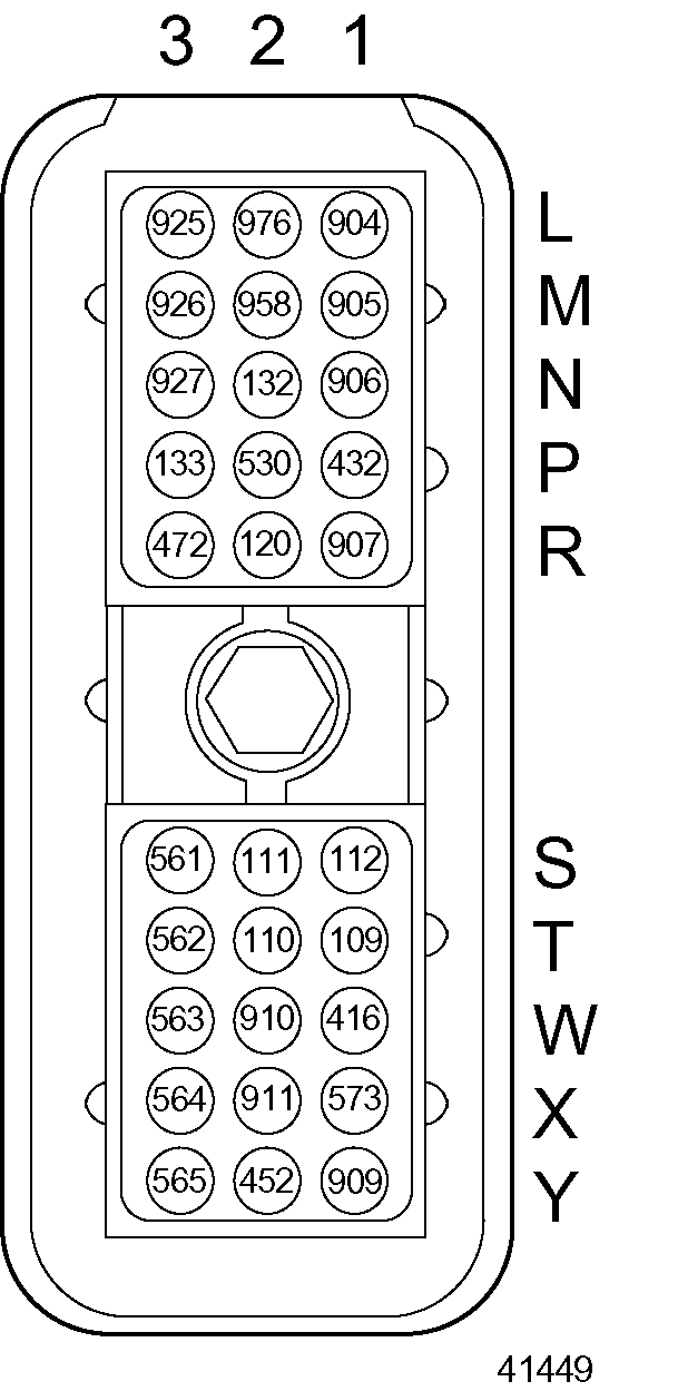
- Check wire 907 (dark green, throttle plate position) cavity R-1 in the Engine Sensor Harness (ESH) 30–pin connector to see if the wire is open ( see Figure
"Engine Sensor Harness 30–pin Connector"
).

Figure 1. Engine Sensor Harness 30–pin Connector
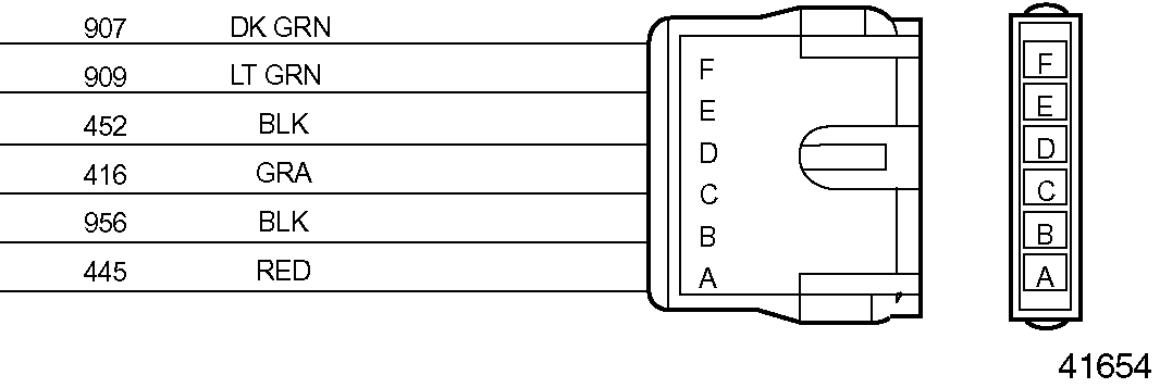
Check pin F (throttle plate position ) in the throttle actuator connector (see Figure "Throttle Actuator Connector" ). Repair or replace any open wires, pins, and sockets.

Figure 2. Throttle Actuator Connector
- If PID 51, FMI 7, Flash Code 65 is still active, go to step .
- If PID 51, FMI 7, Flash Code 65 is no longer active, refer to "5.7.4 Verification" .
- Check wire 907 (dark green, throttle plate position) cavity R-1 in the ESH 30–pin connector for a short to wire 956 (black, throttle actuator ground) in the throttle actuator connector (see Figure
"Engine Sensor Harness 30–pin Connector"
). Also check pin F (throttle plate position) in the throttle actuator connector, and pin B (throttle actuator ground) in the throttle actuator connector. If there is a short, repair or replace the wire(s), pins, and sockets.
- If PID 51, FMI 7, Flash Code 65 is still active, go to step .
- If PID 51, FMI 7, Flash Code 65 is no longer active, refer to "5.7.4 Verification" .
- Check wire 907 (dark green, throttle plate position) cavity R-1 in the ESH 30–pin connector for a short to wire 416 (gray, sensor supply 5VDC) cavity W-1 in the ESH 30–pin connector (see Figure
"Engine Sensor Harness 30–pin Connector"
). Also check pin F (throttle plate position) and pin C (sensor supply, +5VDC) in the throttle actuator connector. If there is a short, repair or replace the wire(s), pins, and sockets.
- If PID 51, FMI 7, Flash Code 65 is still active, go to step .
- If PID 51, FMI 7, Flash Code 65 is no longer active, refer to "5.7.4 Verification" .
- Check wire 416 (gray, sensor supply, 5VDC) cavity W-1 in the ESH 30–pin connector to see if it is open (see Figure
"Engine Sensor Harness 30–pin Connector"
). Also check pin C (sensor supply, +5VDC) in the throttle actuator connector. Repair or replace any open wires, pins, and sockets.
- If PID 51, FMI 7, Flash Code 65 is still active, go to step .
- If PID 51, FMI 7, Flash Code 65 is no longer active, refer to "5.7.4 Verification" .
- Check wire 416 (gray, sensor supply, 5VDC) cavity W-1 in the ESH 30–pin connector for a short to wire 956 (black, throttle actuator ground) in the throttle actuator connector (see Figure
"Engine Sensor Harness 30–pin Connector"
). Also check pin C (sensor supply, +5VDC) in the throttle actuator connector, and pin B (throttle actuator ground) in the throttle actuator connector. If there is a short, repair or replace the wire(s), pins, and sockets.
- If PID 51, FMI 7, Flash Code 65 is still active, go to step .
- If PID 51, FMI 7, Flash Code 65 is no longer active, refer to "5.7.4 Verification" .
- Check wire 909 (light green, PWM No. 2 out) cavity Y-1 in the ESH 30–pin connector to see if it is open (see Figure
"Engine Sensor Harness 30–pin Connector"
). Also check pin E (PWM No. 2 out) in the throttle actuator connector. Repair or replace any open wires, pins, and sockets.
- If PID 51, FMI 7, Flash Code 65 is still active, go to step .
- If PID 51, FMI 7, Flash Code 65 is no longer active, refer to "5.7.4 Verification" .
- Check wire 909 (light green, PWM No. 2 out) cavity Y-1 in the ESH 30–pin connector for a short to wire 956 (black, throttle actuator ground) in the throttle actuator connector (see Figure
"Engine Sensor Harness 30–pin Connector"
). Also check pin E (PWM No. 2 out) and pin B (throttle actuator ground) in the throttle actuator connector. If there is a short, repair or replace the wire(s), pins, and sockets.
- If PID 51, FMI 7, Flash Code 65 is still active, go to step .
- If PID 51, FMI 7, Flash Code 65 is no longer active, refer to "5.7.4 Verification" .
- Check wire 445 (red, throttle body power) pin A in the throttle actuator connector (see Figure
"Engine Sensor Harness 30–pin Connector"
). Also check pin D (throttle body power) in the OEM Power Harness (male/female connection).
- If PID 51, FMI 7, Flash Code 65 is still active, go to step .
- If PID 51, FMI 7, Flash Code 65 is no longer active, refer to "5.7.4 Verification" .
- Check wire 445 (red, throttle body power) pin A in the throttle actuator connector for a short to wire 956 (black, throttle actuator ground) and pin B in the throttle actuator connector (see Figure
"Engine Sensor Harness 30–pin Connector"
). Also check pin D (throttle body power) in the OEM Power Harness (male/female connection) and pin B (throttle actuator ground) in the OEM Ground Harness (male/female connection). If there is an open wire, repair or replace the wire(s), pins, and sockets.
- If PID 51, FMI 7, Flash Code 65 is still active, go to step .
- If PID 51, FMI 7, Flash Code 65 is no longer active, refer to "5.7.4 Verification" .
- Check wire 956 (black, throttle actuator ground) pin B in the throttle actuator connector to see if it is open . (see Figure
"Engine Sensor Harness 30–pin Connector"
). Also check pin B (throttle actuator ground) in the OEM Ground Harness (male/female connection).
- If PID 51, FMI 7, Flash Code 65 is still active, go to step .
- If PID 51, FMI 7, Flash Code 65 is no longer active, refer to "5.7.4 Verification" .
- Check the throttle plate actuator alignment using the bolt tightening sequence (refer to "5.7.2 Bolt Tightening Sequence" ).
Section 5.7.2
Bolt Tightening Sequence
Loosen the bolts using the following sequence:
- Loosen the four bolts that attach the intake elbow to the rear of the throttle.
- Loosen the four bolts that attach the Mixer/PSV assembly to the front of the throttle
- Loosen the two bolts that attach the low pressure regulator to the intake elbow.
- Loosen the four bolts that attach the throttle to the throttle bracket.
Tighten all the bolts using the following sequence:
Note: Torque for all bolts is 34 N·m (25 ft·lb).
- Tighten the two bolts from the throttle bracket to the gear case.
- Tighten the one bolt from the throttle bracket to the cylinder head.
- Tighten the four bolts from the Mixer/PSV assembly to the throttle.
- Tighten the four bolts from the throttle to the inlet elbow.
- Tighten the two bolts from the IMPCO regulator.
- Tighten the two bolts from the throttle bracket to the inlet elbow.
- Tighten the four bolts from the bottom of the throttle bracket to the throttle.
- If PID 51, FMI 7, Flash Code 65 is still active, replace the throttle plate actuator (refer to "5.7.3 Replacement of the Throttle Actualor" ).
- If PID 51, FMI 7, Flash Code 65 is no longer active, refer to "5.7.4 Verification" .
Section 5.7.3
Replacement of the Throttle Actualor
The throttle actuator (see Figure "Throttle Actuator for the Series 60G Engine" ) is non-serviceable and should be replaced as a unit.

Figure 3. Throttle Actuator for the Series 60G Engine
Section 5.7.3.1
Removal of Throttle Actuator
Remove the throttle actuator as follows:
- Vent the fuel system.
- Disconnect and remove the six-wire power harness connectors from the throttle actuator.
- Remove the four bolts connecting the throttle actuator to the mounting bracket.
- Remove the eight bolts attaching the throttle to the inlet and outlet tube assemblies.
Section 5.7.3.2
Installation of Throttle Actuator
Install the throttle actuator as follows:
- Secure the throttle actuator to the mounting bracket with the four bolts and torque to 20 N·m (15 lb·ft).
- Connect the six-wire power harness.
- Install a new gasket and attach the outlet tube assembly using four bolts.
- Install a new gasket and attach the inlet tube assembly using four bolts.
- Run engine and check for air or air and fuel mixture leaks at the throttle and connecting hoses.
- If the code is still active, call Detroit Diesel Technical Service.
- If the code is no longer active, refer to "5.7.4 Verification"
Section 5.7.4
Verification
Verify that troubleshooting was successful as follows:
- Check the DDR to see if PID 51, FMI 7, Flash Code 65 is still active.
- If the code is still active, go to step 2.
- If the code is not active, troubleshooting is complete.
- Call Detroit Diesel Technical Service.
| Series 50G and 60G Troubleshooting Guide - 6SE482 |
| Generated on 10-13-2008 |