Section 5.20
PID 106, FMI 0, Flash Code 47, Intake Manifold Pressure High
The intake manifold pressure is high due to a faulty Manifold Absolute Pressure (MAP) Sensor or incorrect turbocharger wastegate setting.
Section 5.20.1
Troubleshooting PID 106, FMI 0, FLASH CODE 47
Troubleshoot as follows:
- Check the MAP Sensor using the DDEC Sensor Tester J 37164 (see Figure
"DDEC Sensor Tester J37164"
).

Figure 1. DDEC Sensor Tester J37164
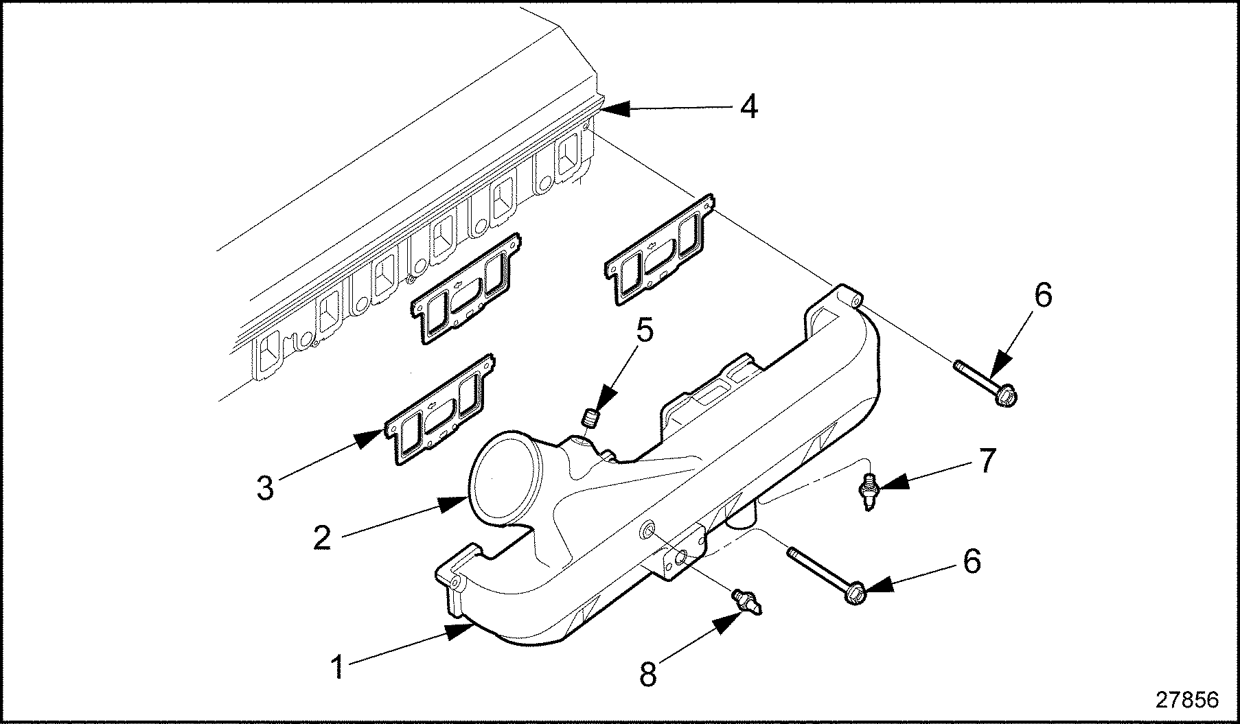
- Disconnect the sensor. The MAP Sensor is threaded into the intake manifold (see Figure
"MAP Sensor Location — Series 60G"
).

1. Intake Manifold
5. Bolt
2. Intake Manifold Inlet
6. Bolt
3. Intake Manifold Gasket
7. ATS (Low Pressure system only)
4. Cylinder Head
8. MAP Sensor
Figure 2. MAP Sensor Location — Series 60G
- Disengage the locking tang on the MAP Sensor connector body. Grasp the terminal body and gently pull it from the sensor.
- Remove the MAP Sensor from the intake manifold.
- Clip the power leads to the 12 volt power source.
- Connect the sensor to the tester at the correct connector.
- Plug in a volt OHM meter. The tester will power up the sensor. Check the values to see if the sensor is operating properly.
- If sensor is faulty, replace the sensor, refer to "5.20.1.1 Replacing the MAP Sensor" .
- If the sensor is not faulty, go to step .
- Check the turbocharger wastegate setting, refer to "5.20.1.2 Turbocharger Wastegate Setting" .
Section 5.20.1.1
Replacing the MAP Sensor
The MAP Sensor is non-serviceable and must be replaced as an assembly. No adjustment is required. Replace as follows:
- Install the MAP Sensor into intake sensor manifold. Torque to 2.4-3.0 N·m (21-26 lb·in.).
- Engage the locking tang on the MAP Sensor connector body.
- Turn the ignition to the ON position. Observe the DDR for any diagnostic code(s).
- If the code is still active, check the turbocharger wastegate setting (refer to "5.20.1.2 Turbocharger Wastegate Setting" ).
- If the code is no longer active, refer to "5.20.2 Verification" .
Section 5.20.1.2
Turbocharger Wastegate Setting
This procedure provides a method for verifying proper wastegate calibration.
- Remove hose from wastegate actuator (for gensets, remove line on top side of can).
- Set-up an indicator at the end of the wastegate actuator adjusting rod to measure actuator rod travel. The indicator should have a minimum travel of 2.54 mm (0.100 in).
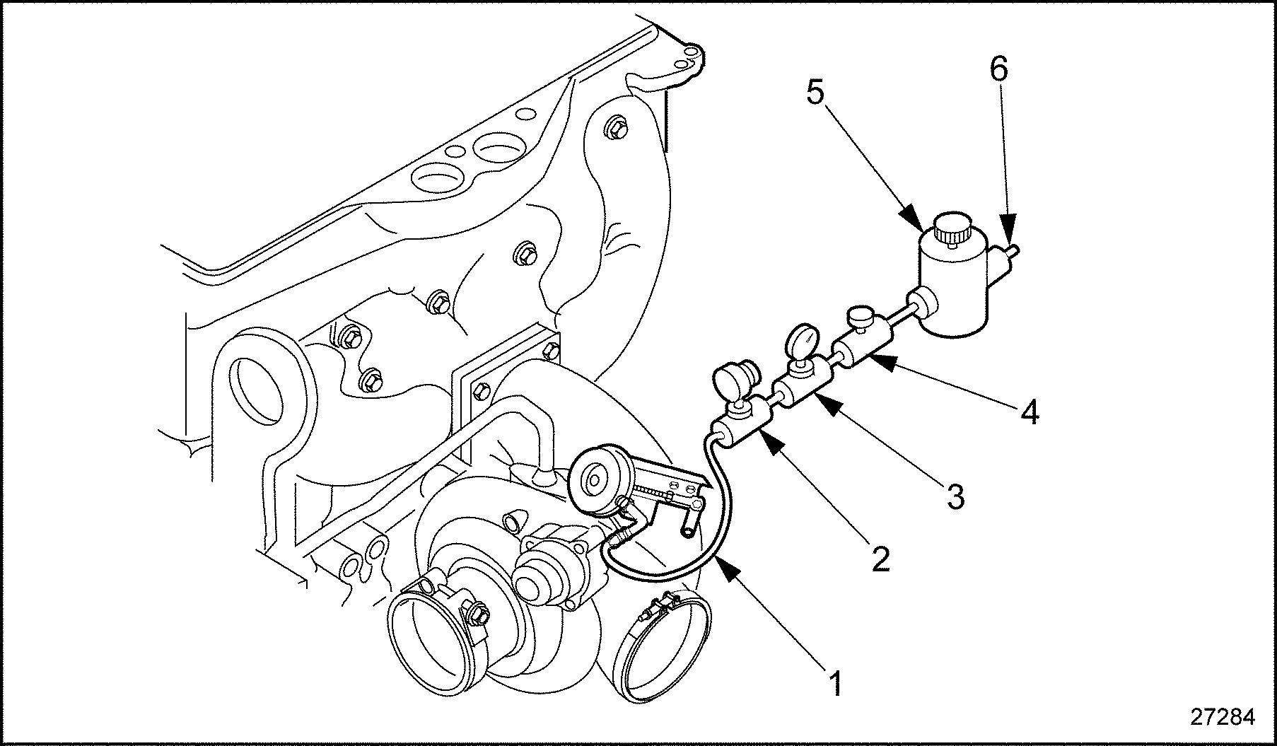
- Connect regulator and pressure gage set-up to wastegate actuator (see Figure
"Wastegate Calibration Equipment Set Up"
).

1. Hose to Wastegate Actuator
4. Supply Air Shutoff Valve
2. Vent Valve
5. Pressure Regulator
3. Pressure Gage
6. Shop Air Supply
Figure 3. Wastegate Calibration Equipment Set Up
- Apply specified calibration pressure (listed in Table
"Wastegate Calibration Pressure at 0.04 in. Rod Travel"
) to the wastegate actuator.
Model
Rating
Set Pressure at 0.04 in. Rod Travel
S50G-Automotive
275 bhp
18.5 psi ± 0.25 psi (short wastegate canister 2 in. in length)
1997-2000 S50G-Automotive
275 bhp
21.0 psi ± 0.25 psi (long wastegate canister 3 in. in length)
2001 S50G-Automotive
275 bhp
22.0 psi ± 0.25 psi (long wastegate canister 3 in. in length)
S50G-150kW-Genset
260 bhp
23.0 psi ± 0.25 psi
S50G-180kW-Genset
300 bhp
31.0 psi ± 0.25 psi
S60G-Automotive
330 bhp
24.0 psi ± 0.25 psi
S60G Automotive
400 bhp
24.0 psi ± 0.25 psi
S60G-General Purpose Stationary
385 bhp
30.0 psi ± 0.25 psi
Table 3. Wastegate Calibration Pressure at 0.04 in. Rod TravelNOTICE:
For genset turbochargers, NEVER apply pressure to bottom part of actuator can. Damage to actuator may result.
- Close air supply shutoff valve. The pressure should hold at the specified pressure. If not, check air hose and fitting connections for leaks. If none are found, replace wastegate actuator assembly. Refer to "5.20.1.3 Removal and Replacement of Wastegate Actuator" .
- Open vent to relieve pressure. Check gage for zero pressure reading. Adjust regulator to zero pressure and close vent valve.
- Adjust dial indicator so it just contacts the actuator rod end and adjust to zero reading.
- Open air supply shutoff valve and slowly adjust regulator until dial indicator reads 0.040 in. Switch pressure on and off, opening and closing supply air and vent valves, to make certain dial indicator travel is from 0.00 in. to 0.040 in. and that the pressure reading is consistent.
- For currently calibrated wastegate actuator, a pressure within ± 0.25 psi of the value listed in Table
"Wastegate Calibration Pressure at 0.04 in. Rod Travel"
will be required to obtain precisely 0.040 in. actuator travel.
- If the pressure required is outside this range, wastegate adjustment is necessary. Refer to "5.20.1.3 Removal and Replacement of Wastegate Actuator" .
- If the pressure required is correct, refer to "5.20.2 Verification" .
Section 5.20.1.3
Removal and Replacement of Wastegate Actuator
This procedure describes the removal of a actuator currently mounted on a turbocharger, the replacement with a new service actuator and setting the pressure adjustment to achieve the correct pressure setting listed in Table "Wastegate Calibration Pressure at 0.04 in. Rod Travel" .
- Remove actuator hose from the top side of the actuator can. With the pressure gage set-up, apply enough pressure to the actuator can until the rod begins to move.
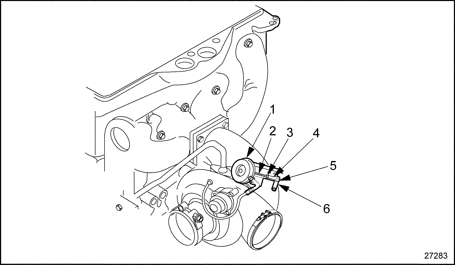
- Remove the retaining clip that holds the actuator rod end on the wastegate lever pin. Lift rod off the wastegate lever pin (see Figure
"Wastegate Adjustment"
).

1. Wastegate Actuator Assembly
4. Adjusting Rod End
2. Locking Collar
5. Retainer Clip
3. Jam Nut
6. Wastegate Lever and Pin Assembly
Figure 4. Wastegate Adjustment
NOTICE:
Never remove the rod end from the wastegate lever pin unless pressure is applied to the top side actuator port; otherwise, damage to the actuator diaphragm may result.
- Remove the lock nuts that secure the actuator can to the base of the actuator bracket, and remove the can from the turbocharger assembly.
- Install the replacement actuator can on bracket; tighten lock nuts.
- Using pressure gage setup, apply enough pressure to the new service actuator can until the rod begins to move.
- Adjust actuator rod end by turning either clockwise or counterclockwise on rod so that the rod end hole lines up with the wastegate lever arm. While the wastegate is held shut, slip the rod over pin.
- Before installing the retaining clip again, the rod end will need to be adjusted to the correct setting. Loosen the jam nut that secures the rod end on the actuator rod. If locking collar is present on the actuator rod, remove and discard collar (see Figure "Wastegate Adjustment" ).
- Remove the retaining clip that holds the actuator rod end on the wastegate lever arm pin.
NOTICE:
For a Genset actuator, NEVER apply pressure to the bottom side of the actuator port. Damage to the actuator may result.
- Using pressure gage setup, apply enough pressure to the top side actuator can port until the rod begins to move, lifting the wastegate valve off of its seal.
- Slip rod end off the wastegate lever arm pin and adjust the rod as needed:
- To INCREASE pressure setting at 0.04 in. turn rod end CLOCKWISE.
- To DECREASE pressure setting at 0.04 in. turn rod end COUNTERCLOCKWISE.
- With pressure still applied to actuator, replace rod end on wastegate lever arm and check the actuator set pressure again.
- If the actuator is still out of adjustment, repeat this procedure.
- If actuator is within specified set pressure, reinstall retaining clip on wastegate lever arm pin.
- Tighten jam nut to secure rod end. For verification, refer to "5.20.2 Verification" .
Section 5.20.2
Verification
Verify troubleshooting as follows:
- Check the DDR to see if PID 106, FMI 0, Flash Code 47 is still active.
- If the code is still active, go to step 2.
- If the code is not active, troubleshooting is complete.
- If the code is still active, call Detroit Diesel Technical Service.
| Series 50G and 60G Troubleshooting Guide - 6SE482 |
| Generated on 10-13-2008 |