Section 14.1
Description of PID 168 — Battery Voltage Outside Normal Operating Range
PID 168 indicates that the PLD-MR control unit has detected engine battery voltage outside the normal operating range.
The diagnostic condition is typically:
- Battery Voltage High (168 03)
- Battery Voltage Low (168 04)
Section 14.1.1
Power Supply
The voltage supply for the PLD-MR is listed in Table "PLD-MR Voltage Supply" .
|
Voltage Supply |
Voltage |
|
|
24 V |
12 V |
|
|
Nominal Voltage |
22 V ≤ V ≤ 30 V |
11 V ≤ V ≤ 16 V |
|
Low Voltage |
8 V ≤ V ≤ 22 V Limited Operating Range |
6.5 V ≤ V ≤ 11 V Limited Operating Range |
|
Overload Switch-Off |
V > 33 V |
V > 33 V |
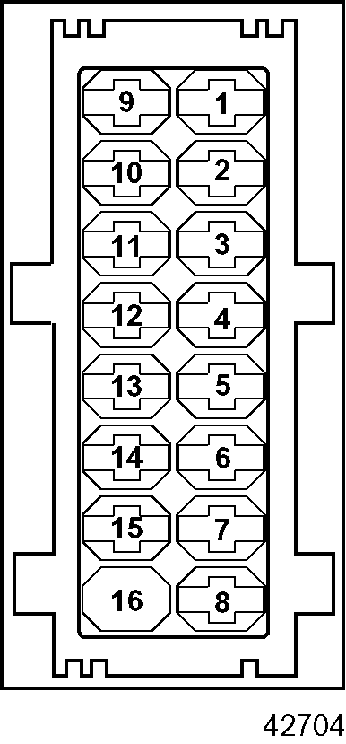
See Figure "PLD-MR Connectors" for the connectors to the PLD-MR.

Figure 1. PLD-MR Connectors
The wiring for the VIH 16-pin connector to the PLD-MR is listed in Table "16-Pin Connector to the PLD-MR" . The side of the connector shown is looking into the pins.
|
Pin |
Signal Type |
Function |
Connector |
|
1 |
Data Link |
CAN Interface (High Line) |
 Front Looking into the Pins on the Harness |
|
2 |
Data Link |
CAN Interface (Low Line) |
|
|
3 |
Data Link |
CAN HF Ground |
|
|
4 |
Data Link |
CAN HF Ground |
|
|
5 |
Power Supply |
Battery Voltage (+) |
|
|
6 |
Power Supply |
Battery Voltage (+) |
|
|
7 |
NC |
NC |
|
|
8 |
Digital Output |
Starter Control Signal |
|
|
9 |
Ground |
Battery Ground (-) |
|
|
10 |
Digital Output |
Proportional Valve 1 – 4 High Side Supply |
|
|
11 |
Ground |
Battery Ground (-) |
|
|
12 |
Digital Output |
Starter High Side Control |
|
|
13 |
Digital Data Link |
Diagnostic Link K-Line (ISO) |
|
|
14 |
Digital Output |
Proportional Valve 3 Low Side Control |
|
|
15 |
Ignition Input |
Ignition |
|
|
16 |
Digital Output |
Proportional Valve 4 Low Side Control |
Section 14.1.2
VIH Power Wiring
The OEM-supplied VIH power wiring (see Figure "Power Wiring" ) supplies 12 volts to the DDEC-VCU and PLD-MR. The terminals are designed to accept 14 AWG standard wire size.
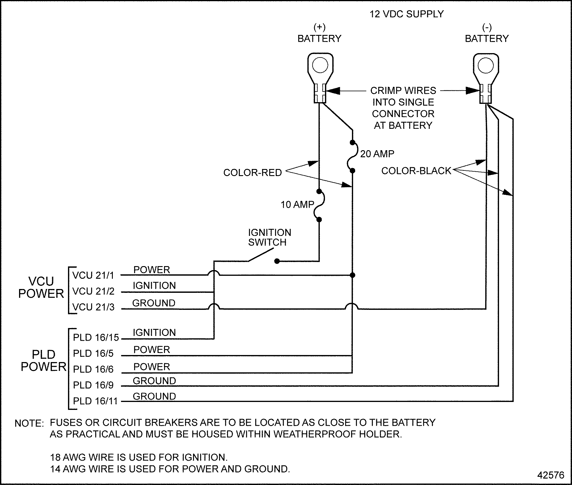
Figure 2. Power Wiring
| MBE 900/4000 Troubleshooting Guide - 6SE422 |
| Generated on 10-13-2008 |