Section 13.4
Troubleshooting Add Coolant Level Sensor
Troubleshooting 111/6, Flash Code 13 follows: Listed in Table "Troubleshooting Add Coolant Level Sensor" , are the flash codes for Add Coolant Level Sensor (ACLS) problems.
|
Flash Code |
PID FMI |
Description |
Typical Cause |
|
13 |
111/6 |
ACLS failed low |
Signal wire (#906) shorted low (ground) |
|
16 |
111/5 |
ACLS failed high |
Open or poor ground; open signal wire |
|
43 |
111/1 |
Coolant level low (ACLS) |
Coolant level below probe |
|
89 |
111/12 |
ACLS Fault |
Coolant reported low on main CLS, with ACLS okay |
Section 13.4.1
Check Sensor
Perform the following steps to check the sensor.
- Unplug the ACLS.
- Start the engine.
- Plug in the DT. Read codes.
- If code 13 (111/6) displays, go to Refer to "13.4.2 Check for Short" .
- If code 16 (111/5) displays, replace the ACLS; then go to test. Refer to "13.4.5 Test Repair" .
Section 13.4.2
Check for Short
Perform the following steps to check for a short:
- Turn ignition OFF.
- Unplug the ACLS module.
- Measure the resistance between cavities A and B of the ACLS connector. See Figure
"Add Coolant Level Sensor Installation"
.
- If the measured resistance is greater than 10 Ω, refer to "13.4.3 Check for Voltage" .
- If the measured resistance is less than 10 Ω, #116 and ground wires are shorted. Repair or replace the wires and test. Refer to "13.4.5 Test Repair" .
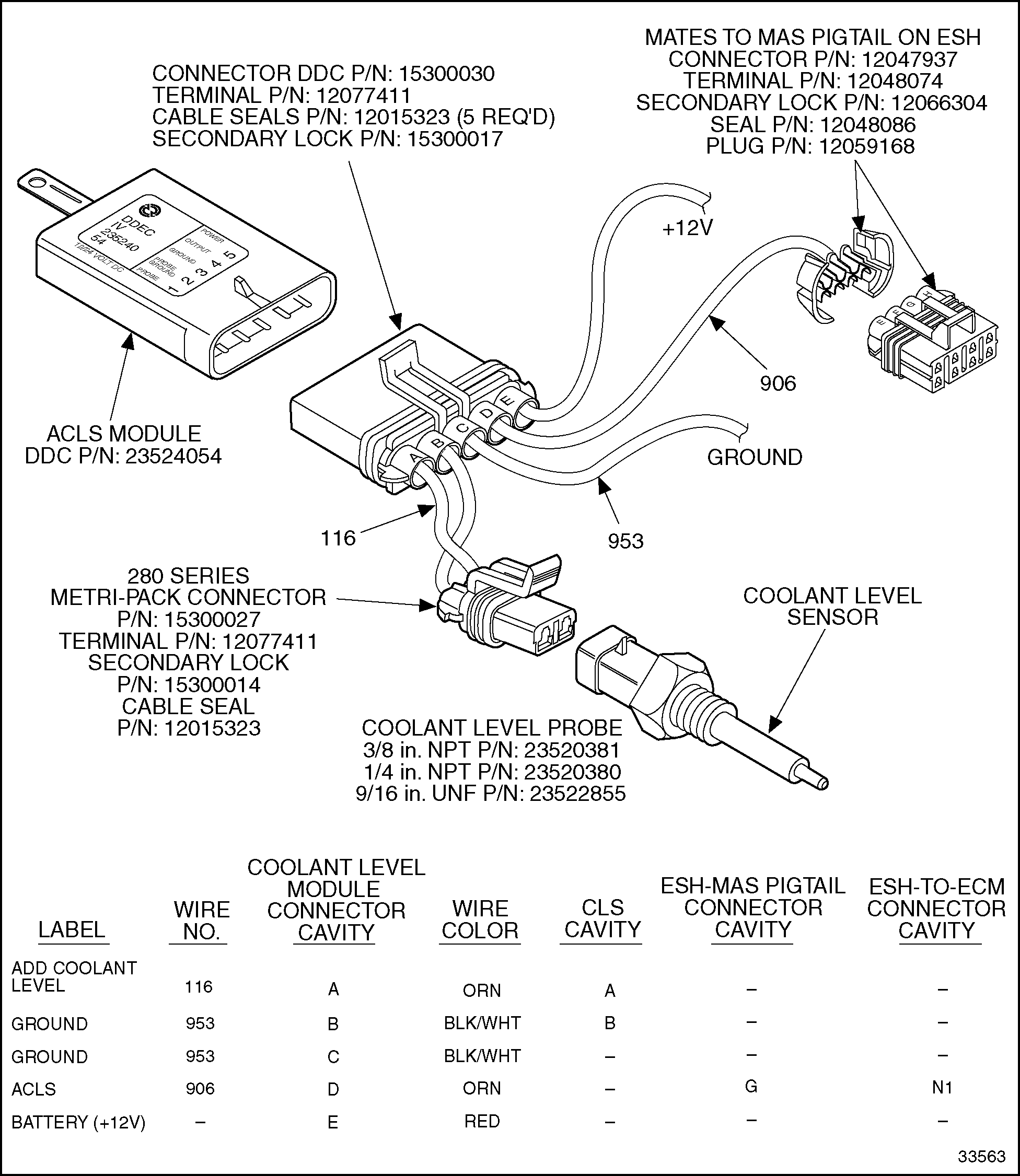
See Figure "MAS Pigtail" for MAS pigtail.Figure 1. Add Coolant Level Sensor Installation
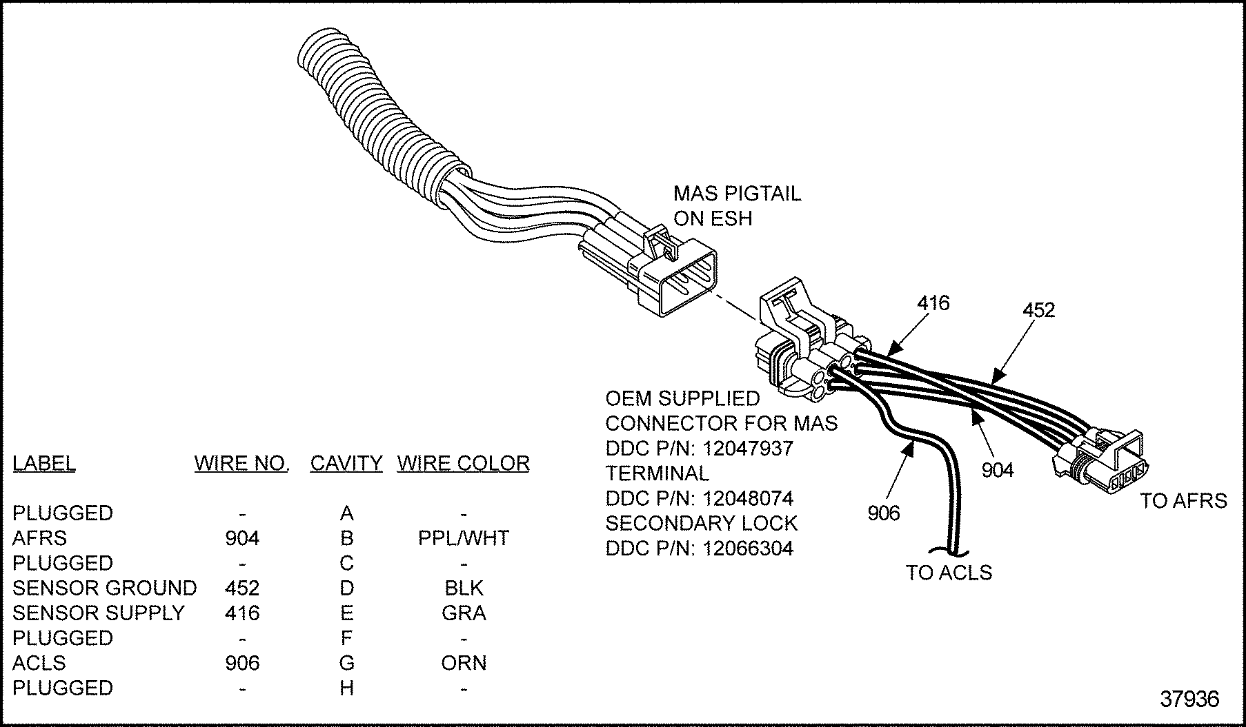
Figure 2. MAS Pigtail
Section 13.4.3
Check for Voltage
Perform the following steps to check for voltage:
- Turn ignition ON.
- Measure voltage between cavities E and C of the ACLS module connector. See Figure
"Add Coolant Level Sensor Installation"
.
- If the measurement is 11.0 volts or greater, refer to "13.4.4 Check for Open Signal" .
- If the measurement is less than 11.0 volts, determine the reason for the loss of ignition voltage.
Section 13.4.4
Check for Open Signal
Perform the following steps to check for open signal:
- Turn ignition OFF.
- Unplug the engine harness 30–pin connector.
- Measure resistance between cavities D and C of the ACLS module connector. See Figure
"Add Coolant Level Sensor Installation"
.
- If the measured resistance is greater than 10 Ω, replace the ACLS module; then, refer to "13.4.5 Test Repair" .
- If the measured resistance is less than 10 Ω, the signal wire is shorted to the battery ground wire. Repair the short; replace the wire. Refer to "13.4.5 Test Repair" .
Section 13.4.5
Test Repair
Perform the following steps to test the repair:
- Connect all the removed connectors.
- Start and run the engine for 5 minutes.
- Plug in the DDR.
- Read the active codes.
- If no codes display, the repairs are complete. Return the unit to service.
- If code 13 displays, troubleshooting is complete; review these steps to find the error.
- If any codes other than code 13 display, refer to "9.1 First Step for Diagnosing a Fault Within the DDEC System" .
| DDEC III/IV Single ECM Troubleshooting Guide - 6SE497 |
| Generated on 10-13-2008 |
Where is the ACLS located on a 1995 freightliner fld120 conventional vin#876028